This may be hugely unwelcome, ✓
In this thread, you and just about everyone else, is welcome and only welcome.
")
Mona's suggestion of a pentode is definitely the way to go, if all the gain is to be lumped into a single stage. While the EF86 is an excellent tube, its S/N performance will be marginal in this application. Superior S/N performance is associated with high transconductance (gm). The EF86 is a low gm type. I suggest the 6AC7 pentode, with its high gm.
In addition to satisfactory S/N performance, linearity is a factor of major importance. Linearity of pentodes is maximized by regulating screen grid (g2) B+.
Gain will be maximized by isolating the pentode from the following RIAA EQ network. Read "MOSFET Follies" and DC couple IRFBC20 source followers to the 6AC7 plates.
As an intelligent fellow named Einstein indicated, simple is good, but not so simple that correct operation is precluded.
Thank you for the tube recommendation and the links. Indeed S/N is important. You seem to offer a good and effective alternative solution
for a quality design.
Powerdac,
There are some unpleasant facts that could easily squelch this project. It has already been pointed out that the RIAA EQ network introduces a 20 dB. insertion penalty at 1 KHz. You want a net gain of 40 dB. That means 60 dB. of gain must be squeezed out of the pentode. See Norton equivalent circuit and understand that pentode gain is approx. = (gm)(net ZL). With a buffering FET, you are going to need 120 Kohm plate load resistors. Plate current is 10 mA. Applying the need for 300 V. on the plate together with Ohm's Law informs us that a (sic) 1.5 KV. B+ rail is needed.
 Also, 12 W. will be dissipated in each of the load resistors. Can you source the 50 W. rated non-inductive resistors a margin of safety requires?
It's not an accident that "typical" phono preamps distribute the net gain across multiple stages.
There are some unpleasant facts that could easily squelch this project. It has already been pointed out that the RIAA EQ network introduces a 20 dB. insertion penalty at 1 KHz. You want a net gain of 40 dB. That means 60 dB. of gain must be squeezed out of the pentode. See Norton equivalent circuit and understand that pentode gain is approx. = (gm)(net ZL). With a buffering FET, you are going to need 120 Kohm plate load resistors. Plate current is 10 mA. Applying the need for 300 V. on the plate together with Ohm's Law informs us that a (sic) 1.5 KV. B+ rail is needed.
Also, 12 W. will be dissipated in each of the load resistors. Can you source the 50 W. rated non-inductive resistors a margin of safety requires?It's not an accident that "typical" phono preamps distribute the net gain across multiple stages.
Last edited:
I just talked to my brother. I transferred what everyone said. He acknowledges that it will not be done. Since things are as they are, he feels safer to make a mosfet 2 stage on his own and then i advised him to either buy a tube kit or fully stuffed board to compare the two.
Are there any tube kits to send him to look at? from members here or outside sources diy?
(From where i stand, i thank you all from prohibiting him doing a mistake and wasting his time and money. )
)
Are there any tube kits to send him to look at? from members here or outside sources diy?
(From where i stand, i thank you all from prohibiting him doing a mistake and wasting his time and money.
)Powerdac, … kilovolts … watts… yowza… It's not an accident that "typical" phono preamps distribute the net gain across multiple stages.
I was trying to avoid that angle since it already might have seemed like my contribution to the discussion was rather pedantic. But you worded it well. It is a problem.
We (some of us, right?) learn fairly early in linear circuit design that the very first stage's irreducible noise makes the greatest contribution overall to the noise on the output (presupposing a very quiet power supply, of course!). Thus, if we have a choice of 3 stages of gain, or 2 … generally designers prefer a fairly high gain, quite low-noise S₁, and aren't as picky about S₂. They'd usually prefer not engaging an S₃ if just for nominal compensatory gain.
That sentiment notwithstanding, I have found in practice that a more graded-gain approach often performs quite well, and rather importantly offers better S/N figure than fewer higher-gain interstages. Hence why I was gently trying to encourage the OP to consider 25× → 6× → ¹⁄₁₀x RIAA → 10× → 1× buffer. Overall is
Gain = ( 25 × 6 × ¹⁄₁₀ × 10 × 1 )
Gain = 150×
dB Gain = 20log₁₀( 150 )
dB Gain = +43.5 dB
VRMS OUT = Gain • VRMS IN
VRMS OUT = 150 × 3 mVRMS
VRMS OUT = 450 mVRMS
If more than that is desired, it is fairly easy to 'tweak' either the 10× S₃ stage gain, with no need to change the output buffer, or even the 6× S2 pre-RIAA gain to the same end.Gain = 150×
dB Gain = 20log₁₀( 150 )
dB Gain = +43.5 dB
VRMS OUT = Gain • VRMS IN
VRMS OUT = 150 × 3 mVRMS
VRMS OUT = 450 mVRMS
Again, thanks for the engaging points.
GoatGuy ✓

Are there any tube kits to send him to look at? from members here or outside sources diy?
Bottlehead offers kit tubed phono stages. They are designed by Paul Joppa, who is competent.
This PCB could provide a path to a lower cost DIY project than Bottlehead. However, you will have to source all sorts of parts and deal with casework.
For your requirement I recommend Allen Wright style gain stage. Replace the first tube with a high gain pentode like D3a, replace 25K ww resistor with CCS, insert a LED in place of R2 and there you go.
View attachment 782275
THX!!!!!
Bottlehead offers kit tubed phono stages. They are designed by Paul Joppa, who is competent.
This PCB could provide a path to a lower cost DIY project than Bottlehead. However, you will have to source all sorts of parts and deal with casework.
thank you for the recommendations. i will pass them to my brother to study them and choose. They seem a much easier way to start into tubes (i guess) for him.
One question to ask is what will the next stage be?
(what is the load Impedance of the next stages input, not just the resistance of the next stage).
The next stage input with a 1 Meg grid resistor, shunted with 60pF of miller capacitance, will cause a -3dB high frequency rolloff at 12kHz, if the preamp output impedance is 220k Ohms.
The same goes for having a long shielded cable from the phono preamp to the next preamp, passive volume control, or power amp.
I measure the capacitance of my shielded cables. There are large ranges of capacitances of 2 foot cables of different manufacturers.
I do like the idea of building one of the kit preamps or tried and tested circuits.
Last edited:
Power Dac:
I don't understand (or did I misinterpret) why were you considering not including RIAA EQ? Were/are you planning on digitalizing the analogue signal and doing RIAA in the digital domain?
Steve
Hi Steve,
I thnk my brother wanted to focus first on the amplification stage as he's absolutely novice with tubes. Tehn he would think about the RIAA. What you say i guess is nice for digitizing vinyl if i am correct?
Power Dac:
I don't understand (or did I misinterpret) why were you considering not including RIAA EQ? Were/are you planning on digitalizing the analogue signal and doing RIAA in the digital domain?
Steve
What you say is nice because i have some vinyl that i would like to digitize for the car. But does it matter how the RIAA will be executed? Is the -20db a penalty both ways? In a passive filter and the same in the digital domain?
I guess the digital domain has an advantage (quality-wise) for not having to pass through the signal from passive components and another advantage of being able to try whatever you want?
thx
Unbelievable article!!!
I don't have the tech know how to understand it fully but the man who wrote it is a very skillful person because he writes in a very simple and comprehensive manner.
Still, it gives me a great place to start and definitely i will be able to digitise.
Thank you!!!!!!!!
You're welcome, duder.
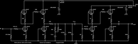
Personally, I build this. The RIAA filter is between the first and second stages.
The filter is designed using standard capacitor and resistor values to make it simple. The 6N1P tubes can be replaced with 6N3P, 6DJ8, 6N5P, 6N14P, 6N23P, 6N24P, or 12AU7 without circuit changes, and there are probably a lot more I am forgetting.
It works amazingly well and costs can be kept low depending on choice of tubes, capacitors, and resistors.
Attachments
- Status
- This old topic is closed. If you want to reopen this topic, contact a moderator using the "Report Post" button.
- Home
- Amplifiers
- Tubes / Valves
- Tube phono stage w/no RIAA components