Hi, I've been looking to add a simple 3 band parametric EQ to a tube bass preamp. My initial idea of making a simple OpAmp based EQ isn't going to fly since the voltage coming out of the tube preamp is clipping the opamps I've been using. I figure if I'm going to end up going to a high voltage op amp I may as well figure out a tube substitute.
The initial design idea for the opamp circuit was Buffer -> noninverting input, while the buffer would also feed a 10k pot, with one leg of the 10k into the non-inverting input and the wiper of the pot going to a series cap, 10kA pot for Q adjustment, opamp gyrator to simulate inductor, then another 1MA pot to sweep the frequency. Basically, it is this simple design here: http://www.geofex.com/article_folders/eqs/parmet.gif
I've been thinking of way to implement this with tubes. Since it will be internal to the preamp, the buffer can be eliminated as it will more than likely be fed from a cathode follower I already have within the preamp itself. Now, I found an old Fender Studio 180W bass amp which uses a 12AU7 cathodyne Phase inverter with 50k pots between anode and cathode, with the wiper going to a CL network. Output is taken from the Anode (similar to the geofex circuit, in which it is an inverting difference amplifier) but the catch 22 is that the fender one seems to have a 4-terminal potentiometer. See schematic here: http://www.albertkreuzer.com/pics/el/studiobass/schem/studiobass.gif
I would like to implement this into my preamp using a 12AX7 stage (have one half of a 12AX7 triode available) but without having to use any special 4-terminal potentiometers. Is there a need for such a potentiometer? Can a normal 3-terminal potentiometer be utilized, with a normal RLC resonant circuit off of the wiper?
I'm also concerned about the inductor portion of the RLC circuit. I know in Mesa Boogie graphic EQs they use actual inductors, would I be forced to do the same or use high voltage op amps for gyrators due to the high voltage of the tube output signals? Having a difficult time finding inductors for such a circuit, at least ones that aren't very expensive.
Also: the 25uf capacitor from the 22k Rk to the 100k Rgrid ... is this bootstrapping the circuit in some way for extra gain or higher Zin? I have not seen a cathodyne with this arrangement before.
I appreciate the help.
Joe
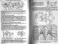
This is something I always wanted to try, never got round to it. Courtesy of the Radio Designer's Handbook, the last circuit seems to be a sweepable centre frequency EQ adjustable from bass+treble cut/boost to mid boost/cut. No noisy inductors, balanced output, could be what you're needing.
Attachments
^ thanks, I'll save that and take a look sometime. At quick glance, it isn't quite what I am after. I already have a passive ladder-style Treb/Mid/Bass tonestack and a recovery stage. The parametric or graphic (depending on what I decide) will be there for further tone tweaks after the passive tone stack.
- Status
- Not open for further replies.