Hi all, after much lurking and reading got inspired to take on my first tube project.
Looking for some guidance with a vintage single ended el84 amplifier. This was pulled from a Motorola record player, the objective is to convert it to a stand alone stereo amp.
I've done the following so far: replaced power cord with grounded 3 prong (no death cap in the circuit that I could see), added on/off switch and fuse holder. Have also replaced all power filter and coupling caps.
I am not intending to use the old volume, tone or balance controls. The amp uses 2 12ax7s in the pre-amp stage, one half of each tube appears to be for gain ("1st AF Amp) and the other is labelled "Tone Amp". Both driver tubes have connections back and forth to the tone control panel.
And this leads me to my question, upon reviewing the wiring and schematic I'm not sure where to wire my inputs for stand alone use? Do I need to use both driver tubes to get adequate gain or can I bypass the 'tone amp' triode section on each channel (if not using the tone controls)? I'm pretty sure there may be some re-wiring involved but looking for the simplest way to get this running.
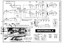
Attaching the schematic, any help much appreciated.
Looking for some guidance with a vintage single ended el84 amplifier. This was pulled from a Motorola record player, the objective is to convert it to a stand alone stereo amp.
I've done the following so far: replaced power cord with grounded 3 prong (no death cap in the circuit that I could see), added on/off switch and fuse holder. Have also replaced all power filter and coupling caps.
I am not intending to use the old volume, tone or balance controls. The amp uses 2 12ax7s in the pre-amp stage, one half of each tube appears to be for gain ("1st AF Amp) and the other is labelled "Tone Amp". Both driver tubes have connections back and forth to the tone control panel.
And this leads me to my question, upon reviewing the wiring and schematic I'm not sure where to wire my inputs for stand alone use? Do I need to use both driver tubes to get adequate gain or can I bypass the 'tone amp' triode section on each channel (if not using the tone controls)? I'm pretty sure there may be some re-wiring involved but looking for the simplest way to get this running.
Attaching the schematic, any help much appreciated.
Attachments
You are correct about a single 'X7 gain stage driving the "final" probably being adequate.
Back in the day, when rectifiers were inexpensive, low cost equipment would abuse them. 40 μF. in the 1st filter position is (IMO) too much for a 5Y3. Clamp mount twin 32 μF./500 WVDC parts, as C15A and C15B, are available that, in combination with a CL-140 thermistor between rectifier and filter, would be much more gentle to both the rectifier and signal tubes. Increase C15C (the reservoir part) to 100 μF. and all should be well.
A 0.068 μF. DC blocking cap. and 100 Kohm grid to ground resistor are needed at the 'X7 section I/Ps. Bypass the 4.7Kohm 'X7 cathode resistors with 100 μF. 'lytics.
Some tweaking, beyond getting it working, is possible. However keep the quality of the O/P "iron" firmly in mind. Beyond simply functioning reasonably well may not be cost justified.
The complexity with adapting that circuit is the way the tone controls are remote, and that one half of each 12AX7 is being used in that remote circuit.
If this was me, since the goal is just to have a single AF gain tube anyway, I'd try and rewire one of the 12AX7's so that both sides are being used in AF gain amp duty. (I might even rewire the other tube socket so it is dedicated in the tone amp role so I could test and prove nothing was broken).
Then the tone amp tube is easy to do away with, once the new circuit without a tone amp is finalised.
The goal is to connect the plates of thsa AF gain amp double triodes to the EL84 coupling caps. But there is plate to plate NFB from the EL84, so it is not trivial to determine all the final component values.
My skills are not so great at this point, but if you presented a schematic without the tone amp included, I am sure the whiskered gurus of this board would step in with recommendations for NFB and coupling components.
It is interesting that that the secondary of the OPT is shorted when there is no speaker connected. Is that an option for protecting an OPT from no load? Or is it only possible because this is an SE amp?
Perhaps it would be worth considering having a switch on the EL84 to toggle triode and pentode modes?
This Motorola looks like an excellent platform, even better IMHO than the popular Magnavox 86xx series because the Moto's OTs have 8 ohm secondaries.I've done the following so far: replaced power cord with grounded 3 prong (no death cap in the circuit that I could see), added on/off switch and fuse holder. Have also replaced all power filter and coupling caps.
Do I need to use both driver tubes to get adequate gain or can I bypass the 'tone amp' triode section on each channel (if not using the tone controls)? I'm pretty sure there may be some re-wiring involved but looking for the simplest way to get this running.
I've attached the Sams for this. It's in pdf and can be enlarged to show greater detail.
It seems you've already replaced the power supply caps and coupling caps. Did you install a replacement can or go with individual caps in the power supply? What values did you use?
Eli's circuit modification advice is spot on, but his concern about the value of the first PS cap is unfounded in this case. The rectifier is not being abused by the 40uf cap.You are correct about a single 'X7 gain stage driving the "final" probably being adequate.
Back in the day, when rectifiers were inexpensive, low cost equipment would abuse them. 40 μF. in the 1st filter position is (IMO) too much for a 5Y3. Clamp mount twin 32 μF./500 WVDC parts, as C15A and C15B, are available that, in combination with a CL-140 thermistor between rectifier and filter, would be much more gentle to both the rectifier and signal tubes. Increase C15C (the reservoir part) to 100 μF. and all should be well.
A 0.068 μF. DC blocking cap. and 100 Kohm grid to ground resistor are needed at the 'X7 section I/Ps. Bypass the 4.7Kohm 'X7 cathode resistors with 100 μF. 'lytics.
Some tweaking, beyond getting it working, is possible. However keep the quality of the O/P "iron" firmly in mind. Beyond simply functioning reasonably well may not be cost justified.
Here's the 5Y3 data sheet: https://tubedata.altanatubes.com.br/sheets/093/5/5Y3GT.pdf
It has three charts showing permissible levels of operation and it states, "With a capacitor-input filter, the conditions of each of Rating Charts 1, 2 and 3 must be satisfied."
Based on the data from the Sams, the use of a 40uf first cap is clearly permissible in this application. In fact you could probably even go up to 47uf safely, as the none of the charts show the stock configuration as being right on the edge.
The only caveat is that the data sheets were developed using what are now called "old stock" tubes. New production versions often don't seem to perform to the same standards. If your amp came with an old rectifier it's probably still in good shape. They were tough and often still test as new. If you're using a modern replacement a 33uf first cap is probably a good idea. The values of the second and third caps are not a concern.
If you used a replacement can you might want to consider using individual caps on future projects. They're significantly less expensive and allow you to choose better specs.
For instance, Eli's suggested F&T 32uf-32uf can from Antique costs $9.95 and the clamp is $1.75, so $11.70 total. It's rated for 2,500 hours at 85 degrees. It's 500v rating is superfluous in this application. The stock 350v rating is more than adequate.
Digi-Key has 33uf 350v Nichicons that are rated for 10,000 hours at 105 degrees for $1.32 each. A United Chemi-Con 100uf 350v with the same hour/temp rating runs $2.44. Both also have better ripple specs than the can.
And Digi-Key has a free shipping option, so you don't end up paying more for shipping than you do for the parts. It's somewhat hidden on their website, here's a link with details: Free Shipping On Parts Orders | Audiokarma Home Audio Stereo Discussion Forums
Attachments
Eli's circuit modification advice is spot on, but his concern about the value of the first PS cap is unfounded in this case. The rectifier is not being abused by the 40uf cap.
I see 20 μF. as "typical" on the GE datasheet and start to worry.
A clamp mounted part retains some of the original cosmetics. An 85o C. rated part sticking up into the (hopefully moving) air will be OK. I completely agree with using 105o C. rated parts on the chassis' underside, as things definitely can heat up. My belt and suspenders mindset says no lower than 400 WVDC, just in case.
Last edited:
My main reason for using individual caps is cost, I'm just a cheap bastard. I just leave the old can in place for looks. Sometimes using a replacement can is unavoidable but it's a last resort for me.I see 20 μF. as "typical" on the GE datasheet and start to worry.
A clamp mounted part retains some of the original cosmetics. An 85o C. rated part sticking up into the (hopefully moving) air will be OK. I completely agree with using 105o C. rated parts on the chassis' underside, as things definitely can heat up. My belt and suspenders mindset says no lower than 400 WVDC, just in case.
That's also why I use Digi-Key as much as possible - free shipping can't be beat and their prices are good.
I usually try to over spec things quite a bit too. I prefer resistors that are rated 5x the actual dissipation, for instance. I just took a quick look at the Sams and the original caps were 350v so I just looked those up. A closer look reveals that there's 310v on that first cap. If I'd paid better attention I'd have suggested a 450v part.
When I first started looking at data sheets, I would blindly follow the data sheet cap values. And I often warned others not to exceed them under any circumstances.
I later became aware that the cap size could be increased if the amp wasn't pushing the tube, but I didn't know how much the cap size could be increased. I just vaguely knew that it could be.
More recently, I took a closer look at the charts and realized they aren't as complicated as I thought. I've also been told that PSUD will at least indicate if the peak current per plate is being violated.
A 0.068 μF. DC blocking cap. and 100 Kohm grid to ground resistor are needed at the 'X7 section I/Ps. Bypass the 4.7Kohm 'X7 cathode resistors with 100 μF. 'lytics.
Thanks all for the guidance. Need some hand holding here. I believe the 'X7 you're referring to is the 2nd half of the tube? So i feed my signal into the "Tone Amp" portion of the 'X7 adding the components indicated and bypassing the 1st half of the tube, do I have it right?
@ FlaCharlie, appreciate the pdf, certainly a much easier read. Being frugal myself I used individual caps, Panasonic 47uf 105c for the filtering and Panasonic PP film for coupling. Kept the can for cosmetics. Adding the caps under the 1 inch high chassis was a challenge, I'll have to build a metal / wood base for it once it's running and adequately tested.
Being frugal myself I used individual caps, Panasonic 47uf 105c for the filtering and Panasonic PP film for coupling.
Put a CL-140 thermistor between the 5Y3 and 1st 47 μF. part, to insure turn on surges are tamed.
Thanks all for the guidance. Need some hand holding here. I believe the 'X7 you're referring to is the 2nd half of the tube? So i feed my signal into the "Tone Amp" portion of the 'X7 adding the components indicated and bypassing the 1st half of the tube, do I have it right?
That will "work", but you are wasting a section of each 12AX7. Rewire things to have a single bottle service both channels and completely disconnect the 2nd socket. Squeeze every last drop out of the OS tubes in your possession. As they run at low plate currents, 12AX7s tend to have long service lives. You could go many years, before buying more 'X7s.
Eli, I usually use a CL80, which is rated to 3A vs 1.1A for the CL140. Specs are about the same otherwise.Put a CL-140 thermistor between the 5Y3 and 1st 47 μF. part, to insure turn on surges are tamed.
But my question involves placement.
I put it on the primary between the fuse and the switch, if there is a switch. I've seen where some people put it on the secondary between the high voltage winding and the rectifier but I don't recall anyone putting it between the rectifier and the first cap.
Is there some advantage to putting it there?
I always figured that putting it on the primary helped not only the high voltage section of the secondary (especially if a directly heated rectifier is used) but also the heater windings and, if present, the bias winding. And it might even reduce stress on the switch.
If placement between the rectifier and cap results in minimum stress on the rectifier, would it be advantageous to use two of them, one after the rectifier and one on the primary? I've heard some people use one on each leg of the primary but never one on each side of the PT.
Last edited:
You would be very well served by triode connecting the EL84. As it is now, performance will be very marginal with the zero feedback pentode setup.
That will "work", but you are wasting a section of each 12AX7. Rewire things to have a single bottle service both channels and completely disconnect the 2nd socket. Squeeze every last drop out of the OS tubes in your possession. As they run at low plate currents, 12AX7s tend to have long service lives. You could go many years, before buying more 'X7s.
Thanks Eli, rewiring to a single 12ax7 may be a little above my noob pay grade but I'll give it a shot.
You would be very well served by triode connecting the EL84. As it is now, performance will be very marginal with the zero feedback pentode setup.
At 1st glance, I thought the same. However, close inspection of the schematic shows short loop NFB from plate to control grid, around the O/P tubes.
If there are significant sonic advantages to switching to triode mode I can give it go while I'm re-wiring the driver tubes.
Any simple "paint by number" type instructions?
Any simple "paint by number" type instructions?
At 1st glance, I thought the same. However, close inspection of the schematic shows short loop NFB from plate to control grid, around the O/P tubes.
Ah, I didn't even notice it. Build on!
The short NFB loop complicates things. FWIW, I'd leave full pentode mode alone.
What can be done, after the unit works reasonably well, is regulating O/P tube screen grid (g2) B+. When power pentode and beam power tetrode g2 B+ is regulated at a fraction of anode B+, open loop linearity is maximized. In particular, highly irritating intermodulation distortion (IMD) is controlled.
I suggest you look at this thread. Much of what's being discussed there can be of use to you. For instance, you are freeing up the space a 12AX7 socket occupies and a 0A2 gas discharge regulator socket could go into the freed space. 😉
Eli, I usually use a CL80, which is rated to 3A vs 1.1A for the CL140. Specs are about the same otherwise.
But my question involves placement.
I put it on the primary between the fuse and the switch, if there is a switch. I've seen where some people put it on the secondary between the high voltage winding and the rectifier but I don't recall anyone putting it between the rectifier and the first cap.
Is there some advantage to putting it there?
I always figured that putting it on the primary helped not only the high voltage section of the secondary (especially if a directly heated rectifier is used) but also the heater windings and, if present, the bias winding. And it might even reduce stress on the switch.
If placement between the rectifier and cap results in minimum stress on the rectifier, would it be advantageous to use two of them, one after the rectifier and one on the primary? I've heard some people use one on each leg of the primary but never one on each side of the PT.
A NTC thermistor between rectifier and PSU filter slows B+ rise down, while allowing the signal tubes' cathodes to start emitting. Maybe thermistors on both the primary and secondary sides of the power trafo are good, but I want signal tube cathode emission to have begun, as B+ is rising. Of course, this discussion applies to directly heated and SS rectifiers. Rectifiers with cathode sleeves exhibit slow B+ rise, due to thermal mass, and a thermistor is not needed.
My thinking for using lower current rated thermistors is to get them safely hot. I don't think we can achieve optimal results at tube mA. current draws, but the "steady state" thermistor resistance should approach 0 Ω. Heat, provided it is not excessive, is useful here. Most of the time, heat is a mortal enemy.
The short loop feedback makes the quality of the output transformer less important.
I'm bothered by the lack of cathode bypass cap, but I suspect some LF rolloff helped play whatever speaker was connected a little more loudly before running out of excursion.
I'm bothered by the lack of cathode bypass cap, but I suspect some LF rolloff helped play whatever speaker was connected a little more loudly before running out of excursion.
Intending to use this with high sensitivity full range drivers, should I be adding a cathode bypass cap to improve the sound / freq range?
Intending to use this with high sensitivity full range drivers, should I be adding a cathode bypass cap to improve the sound / freq range?
It's (IMO) unclear. I suggest you leave the O/P stage be. Omitting a cathode resistor bypass cap. introduces local current NFB, AKA degeneration. At a price of reduced gain and increased O/P impedance, distortion is reduced. The short loop voltage NFB around the O/P tube reduces distortion, reduces gain, and lowers O/P impedance. The loss of gain is easily made up in the preceding voltage amplification stage. As the 12AX7 is reasonably linear, without help, adding a cathode resistor bypass cap. eliminates degeneration there. Remember, factory original employs 2 voltage gain stages, but losses in the frequency shaping circuitry had to be made up, along with adequately driving the "final".
Every setup is a compromise among factors. Here, we're looking for low net distortion and adequate overall gain.
It's not very difficult really.Thanks Eli, rewiring to a single 12ax7 may be a little above my noob pay grade but I'll give it a shot.
If you look at the Sams you'll notice that the two sections of V1 and V2 are wired differently. They are labelled V1A and V1B, V2A and V2B. What he's suggesting is that you eliminate one of the 12AX7s entirely and then rewire the remaining one so that both of its sections are the same.
Specifically, both sections of the remaining 12AX7 should be wired like the what is shown as V1B and V2B. This only involves rewiring one section. So you'll leave pins 1, 2 and 3 as they are and rewire pins 6, 7 and 8 the same as 1, 2 and 3.
Then, coming from each of your input jacks, you put a 0.068 uf cap in series with the grid of each section (pins 2 and 7) and then, from some point between the cap and the pin you add a 100k grid leak resistor to ground.
In his earlier post Eli suggested adding a cathode bypass to the newly rewired 12AX7. Frankly, I'm confused by his latest post. It seems he's saying not to use a cathode bypass on the 6BQ5 output tube but that the 12AX7 should be bypassed.It's (IMO) unclear. I suggest you leave the O/P stage be. Omitting a cathode resistor bypass cap. . . . The loss of gain is easily made up in the preceding voltage amplification stage. As the 12AX7 is reasonably linear, without help, adding a cathode resistor bypass cap. eliminates degeneration there.
If so, you just add a 100uf cathode bypass cap across (in parallel with) the 4.7k resistor. Since there is only 2v on the cathode you can use a very low voltage cap. A 6.3v Nichicon rated for 5000 hrs at 105 degrees is 64 cents at Digi-Key.
- Home
- Amplifiers
- Tubes / Valves
- Tube noob - help with vintage el84 conversion