My question is how it was working since you need both triodes in V2 ?
If you build it right now is a different story
If you build it right now is a different story
Last edited:
Wrong PCB , is not for 12AX7 but 6DJ8 or similar tubes
Maybe soviet 6N2P that is close for gain , if you asked the manufacturer probably they will tell you
Maybe soviet 6N2P that is close for gain , if you asked the manufacturer probably they will tell you
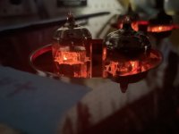
The output stage uses only 1 triode, if only one filament is lit.
That makes the cold output triode into a set of parasitic capacitances in parallel with the lighted triode, if indeed the two output tubes grids, cathodes, and plates are wired in parallel. And, that makes the output impedance 2X as high as two triodes. This preamp was never made to use a 12AX7 in the output socket; And a parallel 12AX7 for the input stage would be lower noise than a single 12AX7 triode, so the input socket was not made for a 12AX7.
A single 12AX7 filament draws 0.150A at 6.3V (the cold filament draws 0.0A)
A 6DJ8 filament draws 0.365A at 6.3V.
A 6922 filament draws 0.300A at 6.3V
An ECC88 or E88CC filament draws 0.356A at 6.3V
More current = less than 8.7V on the filament
Pick up some new tubes (that use pin 9 as a shield, and that usually require grounding of pin 9.
Who installed 12AX7 tubes in a socket that was made for something like a 6DJ8?
Just my $ 0.02 worth (my 2 cents worth).
Last edited:

Parallel tubes would make sense for the input stage ... lower noise . Like that I doubt is a good design anyway
The unused triode could have beed used for a low impedance cathode follower output stage
The unused triode could have beed used for a low impedance cathode follower output stage
Update: the manufacturer got back to me finally. This unit uses 1/2 of 12AX7 in stage 1 and 6N1P in stage 2. Filament voltage is now 6V3 on 1/2 of 12AX7 (other half dark) and 6.3V on the 6N1P. All good on the filament supply. So that's sorted. I put some labels on the unit so prevent this problem for any future owners.
I replaced all the electrolytic caps while waiting for some info on this one.
I tried different tubes on the bench and put a 1kHz sine wave in to measure the output. My goal was to get the best tube matches in-situ. So far so good. Sound is great now.
Now the problem, which takes me back to a fundamental question.
I put the unit into a system and play vinyl. Sounds great. Sometime over the course of 36 hours of being powered up the left channel output comes down. I didn't measure with a meter. Sound is there, but image is right of center. 6dB down?
I swapped to next best tube config on my list of tubes. Again, center image, even levels. It's going into the next 48 hour run now.
What might cause a channel to drift down in level? The 1/2 12AX7 thing?
I didn't replace the film caps. They're RIFA's, the yellow ones in clear cases. I read some of those can fail spectacularly in hot test equipment. I don't imagine this tube unit gets too hot because the tubes are on top, and this chassis is quite large for a 4 tube setup. And the PSU is external. I'm tempted to simply replace all the RIFA's with fresh WIMA's or Kemet's. But before I just throw more parts at this thing, what could cause the one channel to slowly drift down in output?
Measure all of the circuit DC voltages, and compare them between the channels when they are imbalanced.
There must be a bad connection in the left channel, triggered by heating up. Not likely to be a bad capacitor.
Also check the filament voltages, just in case that's the problem.
There must be a bad connection in the left channel, triggered by heating up. Not likely to be a bad capacitor.
Also check the filament voltages, just in case that's the problem.
Last edited:
In going through the unit I sketched out the schematic and was looking to learn a bit more about the design. The RIAA EQ components don't look like the "standard" passive or split circuits on RIAA calculator tools. I'm pretty sure this is a low-production volume commercial unit. I stripped out the measured voltages and component values to protect the IP of the manufacturer.
Does anyone know a similar design I can study? Is there a calculator, spreadsheet, or website with more info?
I think none of the calculators in post #2 are applicable, but one can calculate the transfer function and solve the required equalization values with standard linear electric network theory. I'll see if I can calculate it this Wednesday, when I'm on the train to work.
The circuit has two negative real zeros, while RIAA equalization requires only one (the one corresponding to the 318 us time constant). That can either mean that they corrected for some roll-off elsewhere in the circuit, or that they believe in the so-called Neumann pole, which is non-existent according to Douglas Self and Wikipedia, see https://en.wikipedia.org/wiki/RIAA_equalization and scroll to "The mythical 'Neumann pole'".
The RIAA EQ components don't look like the "standard" passive or split circuits on RIAA calculator tools.
Does anyone know a similar design I can study? Is there a calculator, spreadsheet, or website with more info?
I wouldn't bother with this RIAA network, it is not a good topology. Better to delete the last series resistor.
There's also no need for the last shunt resistor, since a passive RIAA has proper HF response without it.
In fact the unnecessary shunt resistor causes HF peaking.
So that leaves a better RIAA, which is the network here instead: https://www.kabusa.com/riaa.htm
Of course, R1 includes the entire source impedance, like the tube, and the grid resistor to ground
located before the RIAA network.
Last edited:
I had time to do the calculation today, see the attachment for the result. If anyone wants the derivation, I'll post some photos of paper with handwritten equations. R1 includes the output impedance of the previous stage and the AC coupling capacitor is assumed to have negligible reactance.
I'm not sure, but maybe this network allows you to get accurate RIAA correction without unusual capacitance values.
I'm not sure, but maybe this network allows you to get accurate RIAA correction without unusual capacitance values.
Attachments
Actually, I am sure now that you can get accurate RIAA correction without needing some very specific ratio between the values of the capacitors. That's an advantage compared to the usual networks.
On the channel to channel problem - I think I've come to the conclusion that 1 set of 4 tubes that shipped to me are ~8 years old and are tired. I also have a set of 4 fresh tubes. Those measure much better on the bench. I'm going to do a 24 hour run on a few different positions to see if things behave as they should. If so I'm happy. Then I can send this unit back to my friend.
It looks like my calculation from post #30 is correct as well as useless. I checked one numerical example (one with R3B = 0) with a pole-zero extraction program and all four to six digits that the program produces matched, but my assumption that the coupling capacitor has negligible reactance is only correct when it is very large compared to the other capacitors, like 100 times larger than the sum of C1 and C1 when you want 1 % accuracy.
The values I used for the check are:
R1 = 119183.428858293 ohm
R2 = 14454.5454545455 ohm
C1 = 22 nF
R3A = 23982.2825587722 ohm
R3B = 0 ohm
C2 = 2.2 nF
To be continued.
The values I used for the check are:
R1 = 119183.428858293 ohm
R2 = 14454.5454545455 ohm
C1 = 22 nF
R3A = 23982.2825587722 ohm
R3B = 0 ohm
C2 = 2.2 nF
To be continued.
I’m on the pin 4/5 and 9 track.
you should be able to checkt the continuity of the tube sockets there: which one has power?
once correct (good fitting tubes will give light on both sides; ) then the power draw will be as intended; and the voltage should drop as expected.
you should be able to checkt the continuity of the tube sockets there: which one has power?
once correct (good fitting tubes will give light on both sides; ) then the power draw will be as intended; and the voltage should drop as expected.
I found a way to approximately include the effect of the AC coupling, see the attachment (an exact solution gets too complicated for me). I still want to put the equations into a spreadsheet and check the result with a pole-zero extraction program, but not now.
Attachments
Marcel: "Things get rather more complicated when there is an AC coupling capacitor of which the reactance is too large to be neglected, or when the output of the amplifying stage has considerable reactance for some other reason, for example because it is a triode stage with cathode decoupling and the cathode decoupling capacitor is not very large"
Off track but interesting:
There is a blog about decreasing the cathode de-coupling cap to the smallest amount possible, and ditto the decoupling of the power supply. An The Ultra (thin) Path to earth. Ale Moglia/Bartola - (new adventures in) ultra‑fi .
Some use LEDS (I did experiment) or diodes. [But I dropped the LED again.]
See the attachments. My approximation is about 0.21 % off in a case where the AC coupling capacitor is 10 times larger than the largest RIAA correction network capacitor. The zip file contains Excel sheets that were actually made with LibreOffice Calc.
Attachments
See https://www.diyaudio.com/community/...age-gain-stages-pros-cons.402222/post-7442425 for an example of the inaccuracy you get when you don't include the AC coupling in the calculation.
Yes, they bulge, crack and can explode. Temperature may play a role, but the manufacturing process was simply flawed, they used paper dielectric, so they gradually absorb moisture and swell, degrade, become electrically leaky, sometimes short out and go bang. The advice is "replace on sight".I didn't replace the film caps. They're RIFA's, the yellow ones in clear cases. I read some of those can fail spectacularly in hot test equipment. I don't imagine this tube unit gets too hot because the tubes are on top, and this chassis is quite large for a 4 tube setup. And the PSU is external. I'm tempted to simply replace all the RIFA's with fresh WIMA's or Kemet's.
- Home
- Amplifiers
- Tubes / Valves
- Tube MC Phono Stage - RIAA Calculator / Formula Help?