Hello everyone,
I have a question regarding the quoted maximum values of tubes in datasheets.
For example, 6L6GC specifies 500V maximum anode voltage. Is this value the maximum operating voltage level (meaning I would design an amp with a B+ of 500V when everything is settled) or a value that should not be ignored even for a transient moment?
I am designing a 2x6L6GC output stage, planning to use 450V B+. I know that the initial B+ voltage before the tubes start to conduct, can reach 495V, which is within limits. But what if the ac home supply rises to 257V as permitted (instead of 230V) and my initial B+ becomes roughly 545V? Will this damage the tube?
For instance, I have seen datasheets of EL34 quoting 800V maximum voltage but 2kV absolute peak voltage. Which makes me think that in a similar manner, all tubes could possibly withstand a 10% surge of their maximum rating until they start conducting, without any damage or loss of life expectancy. Is this valid?
The 2Kv rating is for the supply voltage, not a peak working voltage like they refer to for rectifiers.
Last edited:
You are probably safe here. The tube is cold when this overvoltage occurs andHello everyone,
I have a question regarding the quoted maximum values of tubes in datasheets.
For example, 6L6GC specifies 500V maximum anode voltage. Is this value the maximum operating voltage level (meaning I would design an amp with a B+ of 500V when everything is settled) or a value that should not be ignored even for a transient moment?
I am designing a 2x6L6GC output stage, planning to use 450V B+. I know that the initial B+ voltage before the tubes start to conduct, can reach 495V, which is within limits. But what if the ac home supply rises to 257V as permitted (instead of 230V) and my initial B+ becomes roughly 545V? Will this damage the tube?
For instance, I have seen datasheets of EL34 quoting 800V maximum voltage but 2kV absolute peak voltage. Which makes me think that in a similar manner, all tubes could possibly withstand a 10% surge of their maximum rating until they start conducting, without any damage or loss of life expectancy. Is this valid?
does het warm.
Do check that caps around the amp is safe, 630Volts in coupling caps etc. Also
make sure the B+ electrolytic is within limits.
In any amplifying stage that is loaded with an inductor, including all output stages feeding an OPT, the plate voltage in NORMAL operation will swing to 2X the B+ voltage before clipping when tested into a resistive load.
In a guitar amp driven to clipping into a speaker operating near it's resonant frequency, I have actually measured over 2KV in an amp that uses a 430 volt B+. That amp was running cheap Chinese 6L6GC's. It never blew up.
The 6L6GC can stand well over 2KV on it's plate. If it fails due to overvoltage the failure is usually inside the phenolic base, not inside the glass. It is usually an arc from pin 3 (plate) to pin 2 (heater) which is often grounded. The same guts used in 6L6 types are put inside 807's and 6BG6's where plate voltages well over 2 KV are common. Here the plate is connected to a cap on the tube.
The internals are capable of more B+ than you are going to feed them. Use good quality sockets in an amp that will see clipping, because the arc often happens inside the socket, not the tube.

Best reply, ever. (TubeLab)
Most people don't realize that transformer primaries work as nice big inductors, resisting the change of current-flow, like all inductors as voltage fluctuates. They're kind of 'anti-B+ supplies', that way. I have long held that the stored energy of the output transformer significantly and unsubtly increases the dynamic range potential of the valve-final amplifier; it may well be “the sound” as often described, especially in the context of very-high-quality recordings reproduction.
NO direct-output amplifier, 99% of them silicon, 1% “OTL” have that stored reactance energy.
In the magnetic 'circuit' of the driven speaker's assortment of magnetic moments, masses, capacitors, resistance, and the distributed inductance of speaker cords, yada, yada (and the output transformer's resonance and winding-to-winding coupling to the primary), … its a wonder it makes proper sound at all!, yet it does, and from persona experience, sometimes astoundingly good music as well.
I've had my ear gravity-checked in fine, fine audiophile shop sound demo rooms; I've listened to electrostatic planars, peaky towers, point-source wonders, you name it. But in the end, comparing a $10,000 (kind of on the low end side!) high-voltage valve amplifier against an equally expensive silicon masterpiece, … its like you are in two different sound studios. Every time. Every single time.
And I always prefer the big ol' 100 pound transformer dominated valve finals.
Always.
Even in 'hidden behind a wall, with double-blind testing procedures' (including quadruple amplifiers, and a systematically randomized testing with intentional mis-direction during the switching).
Every time.
Or in the legendary words of someone I just made up, “its the transformer, stupid!”.
⋅-⋅-⋅ Just saying, ⋅-⋅-⋅
⋅-=≡ GoatGuy ✓ ≡=-⋅
Last edited:
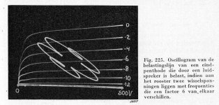
Some measurements on a single EL41 with 250 V anode and screen supply voltage and with a low quality OPT (dc-resitance of the primary = 300 Ohm and inductance of the primary = 5 Henry) and driven just to the point where controlgrid current would start to flow. The anode voltage reaches 1900 V at peaks!
Attachments
Last edited:
...and from personal experience, sometimes astoundingly good music as well.
It's not that hard...
Many thanks for all your helpful replies! So I will power them up without fear. 🙂
If the mains voltage at where you live rises from 230 V to 257 V (does it really?) and stays there for some time, than you should be carefull.
If the power tubes in your amplifier are biased (close) to their maximum dissipation rate (class A or AB; mostly by cathode bias) or are biased 'at their edge' when driven with fixed bias (class AB or B, where the limit is the maximum average dissipation at any point of operation) than you could run into problems, either by violating the maximum dissipation with no signal (class A or AB with cathode bias) or violating the maximum average dissipation (class AB or B with fixed bias) at zero, or at full signal (in class B you have a point of operation somewhere half of full power where the average dissipation of the tube is at its lowest).
I can't resist.
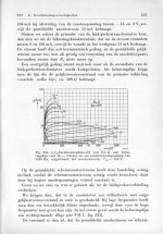
This is the measured loadline of a power pentode, with a real-life load (OPT and loudspeaker, so a complex load) which is driven with two frequencies of equal amplitude but with frequencies which differ from each other by a factor of 6.
This is the measured loadline of a power pentode, with a real-life load (OPT and loudspeaker, so a complex load) which is driven with two frequencies of equal amplitude but with frequencies which differ from each other by a factor of 6.
Attachments
Last edited:
PCL200,
Thanks!
I remember decades ago when an engineer mentioned a single elliptical load line on an output tube. I think about that issue often.
But I never before saw a graph of a dual tone elliptical load . . . a great way to "see" the result.
And then a graph with music too!
Thanks!
I do think that for amplifiers that do not have negative feedback . . .
Generally triodes or triode-wired pentode/beam tubes in push pull respond much better to an elliptical load, versus how a single ended amp responds to an elliptical load.
Just my opinion.
And yes, I do design, build, and listen to, and like both single ended and push pull amplifiers.
Thanks!
I remember decades ago when an engineer mentioned a single elliptical load line on an output tube. I think about that issue often.
But I never before saw a graph of a dual tone elliptical load . . . a great way to "see" the result.
And then a graph with music too!
Thanks!
I do think that for amplifiers that do not have negative feedback . . .
Generally triodes or triode-wired pentode/beam tubes in push pull respond much better to an elliptical load, versus how a single ended amp responds to an elliptical load.
Just my opinion.
And yes, I do design, build, and listen to, and like both single ended and push pull amplifiers.
Last edited:
I remember decades ago when an engineer mentioned a single elliptical load line on an output tube.
Just remember that that load LINE that you see on paper, only exists on paper, usually in textbooks.
Real amps have elliptical load "lines" that vary with frequency and amplitude, hence the white "ufo" in the picture.
When you remove the nice resistor across the output and attach a speaker, then play some music, the result looks like a 4 year old with a crayon got at the paper.
Tubelab_com,
And that is why the engineer "lowered the boom" on me over 35 years ago,
when he mentioned the elliptical load line to me.
I wonder how many have ever taken their amplifier, applied a Small square wave at the input, and then looked at the output:
Unloaded
Resistor loaded
Loudspeaker loaded
(not you Tubelab, you have tried everything at least twice) - Just a little British understatement.
Like sports, it is "The Best of 3".
Remind me, what does the load line of a cell phone antenna look like when it is in speaker mode and sitting on a wood table?
Now, what does the load line of the cell phone antenna look like when it is covered by your hand on one side, and your ear and face on the other side?
Last edited:
With valves, you also have design centre ratings and absolute maximum ratings. The design centre ratings are somewhat conservative values that have some safety margin built in for mains voltage and component tolerances.
Slightly off-topic, the maximum heater-cathode voltage rating is related to some slow electrolysis process rather than normal dielectric breakthrough, see Rodenhuis, Santing en Van Tol, "The life and reliability of valves", Philips Technical Review, vol. 18 (1956-1957), number 7, pages 181...216, December 1956 (available on internet somewhere).
Slightly off-topic, the maximum heater-cathode voltage rating is related to some slow electrolysis process rather than normal dielectric breakthrough, see Rodenhuis, Santing en Van Tol, "The life and reliability of valves", Philips Technical Review, vol. 18 (1956-1957), number 7, pages 181...216, December 1956 (available on internet somewhere).
Tubelab, you have tried everything at least twice
what does the load line of a cell phone antenna look like when it is in speaker mode and sitting on a wood table?
Relatively close to a 50 ohm resistive load.
Now, what does the load line of the cell phone antenna look like when it is covered by your hand on one side, and your ear and face on the other side?
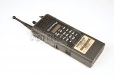
I have done that one too.....far more than twice, starting as a rookie two way radio transmitter engineer in 1984 working on the STX police walkie talkie (picture).
There were three different antennas offered. I took a radio apart lifted the connection to the RF power amplifier and attached an RF network analyzer set up to display the actual impedance presented to the RF power amp by the antenna and its associated electronics, the 2 inch cable and the transmit / receive switch. The ideal antenna would present a 50 ohm resistive load to the power amp, just as a resistive test load should present an 8 ohm load to an audio amp.
Just as a real speaker with some speaker wire, a driver or three, and maybe a crossover presents a varying impedance with respect to frequency and input material, a radio antenna will present a varying impedance with respect to frequency and its surroundings.
The load presented to the RF power amp is displayed on a Smith chart, which shows resistance and inductive or capacitive reactance. A perfect 50 ohm resistive load for all tested frequencies is a single dot in the middle of the chart. Any other load moves the dot in a direction away from center with a dead short on the left end of the horizontal axis and an open circuit on the right end. A pure capacitance is at the top of the vertical axis, with a pure inductance at the bottom.
I found that with enough time and patience you can fill the entire chart black with a clear border around it's outer edge. This clear border represents the losses between the antenna and the power amp. Lower losses makes for a larger circle of "mismatch." The short stubby antenna on the STX radio could hit every possible mismatch out to an 8:1 VSWR. Most cell phones are similar. We used this data to simulate "nasty antennas."
Here, about 25 years later I am torturing a high power (100 watts peak) LTE RF power amp intended for the trunk of a cop car with a simulated 8:1 circle of mismatch in a temperature chamber set up to simulate "black sedan trunk in the Florida sun with the officer's jacket thrown over the radio," about 75 degrees C. The metal rod sitting on the power supply that is on top of the temp chamber is a "trombone line." It is a special 50 ohm transmission line that slides like a trombone. It is essentially a variable length piece of coax cable. The black thing is a 400 ohm (8:1 mismatch) load.
Attachments

Tubelab,
I am getting old; I had not thought of the smith chart for a long time.
We used to say that "The return loss is so bad, that the trace is running Outside of the smith chart circle". - Which is impossible, but the other people got the idea that we meant that it was not a very good match.
Then, in the underground glass fiber world, when the digital signal went away . . .
We would say: "That backhoe is cutting up the neighborhood again".
That was called "Backhoe Fading". Ha Ha
The reflection was easy to find using an OTDR, then looking for the loose earth.
A simple way to locate without any equipment was to look for the "Optical Fiber Cable - Do Not Dig Here" Sign.
That is usually near to where they decided to dig.
Last edited:
With valves, you also have design centre ratings and absolute maximum ratings. The design centre ratings are somewhat conservative values that have some safety margin built in for mains voltage and component tolerances.
Slightly off-topic, the maximum heater-cathode voltage rating is related to some slow electrolysis process rather than normal dielectric breakthrough, see Rodenhuis, Santing en Van Tol, "The life and reliability of valves", Philips Technical Review, vol. 18 (1956-1957), number 7, pages 181...216, December 1956 (available on internet somewhere).
Link to that article (p.181-216) : http://nvhrbiblio.nl/biblio/tijdschrift/Philips%20Technical%20Review/Philips-Technical-Review-1956.pdf
the trace is running Outside of the smith chart circle". - Which is impossible,
When living in the theoretical paper world is is impossible to run a trace outside the boundary of the Smith chart. In the real world with a network analyzer on a live circuit, it happens.....especially on some of my stuff.
If the analyzer is properly calibrated to the measurement plane, it means that your circuit is highly unstable or actually oscillating.
My old HP8753C is especially easy to fool. A really unstable, but not quite oscillating amplifier can fill the chart with "confetti" that moves when you touch the circuit board (cheap Amazon sourced 2 GHz amp board).
It's just to the right of my head in this picture. I recently got one of those "Nano VNA's" from Ebay that costs about $75. Preliminary testing shows that it does work, and will be a lot easier to carry outside and use for antenna measurements than this 40 pound beast with a dim CRT.
Attachments

- Home
- Amplifiers
- Tubes / Valves
- Tube maximum voltages