I would like to build Frank's Ultimate Preamp using the 6sn7 tubes, but it would have too much gain. In researching this site, I found a thread started by Merlin el Mago: https://www.diyaudio.com/forums/tubes-valves/227387-lundahl-ll1660-opt-franks-6sn7-linestage.html
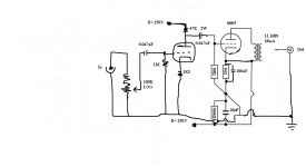
With the help of Thomas Mayer, he came up with the attached circuit for a headphone amp.
In trying to spec the output transformer, Thomas told him to double the plate current if the two tubes were in parallel and not double it if the tubes were in series. It is not clear to me what the current through the transformer will be. Mago posited that it would be 8ma, but I am not sure.
Could someone point out how to calculate the current through the transformer? Also, any thoughts on whether this circuit would be a good one for getting lower gain out of a 6sn7 would be appreciated.
By the way, I would like between 6 and 12 db or so for my line stage.
Thanks for any help anyone can give me.
Jazzzman
Attachments
Exactly zero. You're feeding both plate and cathode with B+.Could someone point out how to calculate the current through the transformer?
Thank you, that sounds like the circuit won’t work! He has b+ on the anode of the first tube and on the cathode of the second tube, should he do that differently? Is the circuit hopeless?
If you would like a line stage preamp, with indirectly heated triodes and output transformer, then Thomas Mayers 6AH4 design should be a good start
VinylSavor: The Octal Preamplifier Mk2: Circuit
If you really want to use 6SN7 his mk1 circuit is also worth a look
Otherwise, go to the 26 preamp thread and use a directly heated triode [emoji16]
VinylSavor: The Octal Preamplifier Mk2: Circuit
If you really want to use 6SN7 his mk1 circuit is also worth a look
Otherwise, go to the 26 preamp thread and use a directly heated triode [emoji16]
Perhaps a little more work required there! And a lot more reading. 😱Otherwise, go to the 26 preamp thread and use a directly heated triode [emoji16]
Thank you sjs and TG. TG, your design looks interesting. The design from Thomas Mayer also looks interesting. I am between the two, but first I have a couple of questions regarding the Thomas Mayer design.
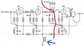
I have attached a copy below. I would only use the line amp portion which is to the right of the red line. I have circled in green the portion that Thomas said decouples the power supply (he is using the same power supply for both channels). He also says that the choke (see arrow) is also used to decouple the power supply. I seem to recall that somewhere he says that the choke could be eliminated. My first question is whether decoupling the power supply is important. I do not recall any discussion anywhere else about any concern of using the same power supply for each channel of a preamp. Any thoughts from anyone?
Secondly, the designs clearly have differences, but I do not understand the significance of them. Does anyone know of any advantages/disadvantages of one approach over the other?
Thanks in advance for any help anyone can provide.
Attachments
It is to some degree.I seem to recall that somewhere he says that the choke could be eliminated. My first question is whether decoupling the power supply is important.
You can use common CRC-filtered supply for both channels.
You can use common CLC-filtered supply for both channels.
You can use separate CLC-filtered supplies for each channel with common rectifier for both (common first capacitor, then separate chokes and second capacitors).
You can even use fully separate (including rectifiers) PSUs for each channel.
You can also go for LCLC, CLCLC or LCLCLC filters, B+ voltage regulators and many other things.
Each step is beneficial. You basically stop when your budget ends 😀
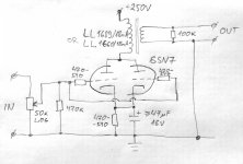
My design is classic common-cathode stage. Thomas' design is commonly known as "ultrapath". They differ essentially just in one thing - where to connect the other side of the cathode bypass capacitor - to the ground or to the B+.Secondly, the designs clearly have differences, but I do not understand the significance of them. Does anyone know of any advantages/disadvantages of one approach over the other?
You can read on the pros and cons of both designs in this TubeCad article:
UltraPath = Ultra-Simple...Except that it's Not
Thank you TG, that article explains a lot! I will give your circuit a try.
And do not forget the Ultrapath line stage from Electra Print:
Electra-Print.com The Ultrapath
I have a question about choosing the output transformer for a simple common cathode line stage like what is under discussion here. I'm hoping my question will help out the OP as well.
If you take a 6SN7, for example, it has a plate resistance of about 8k ohms.
If you use that with an OPT having a 10k ohm primary, won't you be heavily loading the 6SN7? (10k ohm load on 8k ohm rp)
But, if you use a 10k:600R output transformer, and load the secondary with a high impedance of let's say 10k ohms, will that change the reflected impedance of the secondary back to the primary?
In other words, are the only things that really matter the stepdown ratio and primary inductance? At least as far as choosing the basic Pri:Sec impedance of your OPT, that is.
Let's say we have a nominal 10k:600 OPT, like the Electra-Print in the previous post.
- The secondary is connected to a 10k ohm load.
- 10,000/600 = 16.67 (the ratio of primary Z to secondary Z)
Does that mean the nominal 10k ohm primary impedance now looks like 166,700 ohms (10,000*16.67) to the 6SN7?
So the important thing is that the primary inductance of the OPT has to be really high, like 130H, to get a -3dB down point at 10Hz, or 65H for -3dB at 20Hz.
I got that by 2piFL
All good?
Next, the stepdown ratio. For a primary to secondary impedance ratio of 10k:600, that's a stepdown ratio of about 4:1. So for 4V into the primary you get 1V out across the secondary load. Correct?
If so, that means for a nominal level of 1V rms across the load, you need the 6SN7 plate to swing 4V rms. With a gain of about 17, that should be 235mV rms to the grid (input of the tube).
If I got that all right, then this looks like it could work very well with a 6SN7 into a 10k:600 output transformer, as long as the primary inductance of the OPT is > 65 Henries.
Does that all look right?
--
It does, except for one thing.Does that all look right?
Many transformers that are rated for particular impedances (say, 10k:600) need to be loaded with the rated value (600 Ohm in this case) to have good frequency response in the HF area. Underloading them may cause a noticeable bump at some-kHz.
Some transformers allow some degree of underloading though. You have to research the particular model to determine its suitability for your application.
In that case, why use a 10k:600 ohm OPT for a line stage that's usually going to see 10k or even 47k load on the secondary? You'd put a 1k ohm resistor across the secondary to load it, right? But now you've got something like a 15k load presented to the 6SN7 plate. That would be too heavy a load on it, right?
So to summarize:
If using an OPT for a line stage:
1) You want to choose a triode with a low rp, so you don't need gobs of inductance from the primary.
2) Low rp triodes are usually going to have low mu, so you don't want too much of a stepdown ratio from your OPT pri:sec.
3) You want the secondary impedance to match the load, or at least as closely as possible.
If the load is going to be 10k, then you want something like a 10k:10k impedance ratio, so you can lightly load the triode you're using, and you can avoid resonance problems from loading the secondary too lightly.
But now what are you getting from the transformer other than galvanic isolation?
I guess what you want is a 40k:10k OPT so you can use a 6SN7 with best results. Or maybe 20k:10k. Or even 10k:5k. But as far as I can tell, none of those exist.
What am I missing here?
--
For that 10k:600 OPT, I'd say use a 6N6P or 5687 as the triode. About 2k ohm rp. Then put a 1k ohm resistor across the OPT secondary to load it down.
Or an exotic high gm RF pentode wired triode.
Right?
Last edited:
I think better to talk in terms of turns ratio, primary inductance, and load impedance.
Those 40k, 20k, 10k, 5k values depend on variables, including frequency and that is why it's better to forget them.
Calculate the required primary inductance, something that provides an impedance >2x Rp at your lowest usable frequency. Use the 'in-circuit Rp' and not static datasheet value. Decide how much gain and at what output impedance you need and determine turns ratio. For voltage gain stages, load the transformer with >10 times the output impedance as seen at secondary, consider the voltage divider action of source to load impedance in your assessment for gain requirement.
Also, consider the winding capacitance impact to HF response and how that might represent a practical limit to primary inductance spec and therefore tube type as relates to in-circuit plate impedance.
HK
Last edited:
Well, there is another interesting effect - the tube's rp itself partially dampens HF resonance.In that case, why use a 10k:600 ohm OPT for a line stage that's usually going to see 10k or even 47k load on the secondary? You'd put a 1k ohm resistor across the secondary to load it, right? But now you've got something like a 15k load presented to the 6SN7 plate. That would be too heavy a load on it, right?
Lundahl, for example, doesn't provide impedance ratios in the datasheets at all - just the voltage (turns) ratios, inductances, DC resistances and recommended minimum source impedances, stating that you should use additional load on the secondary if your source impedance is lower than recommended.
True. That's why I used both 6SN7 halves in parallel in my design above. That would have rp slightly under 4k, and LL1660/LL1689 need 3k or more for 4.5:1 connection - that 100k on the secondary is there just because I don't like secondaries hanging in the air when the device is not plugged to what it's intended to drive.1) You want to choose a triode with a low rp, so you don't need gobs of inductance from the primary.
Not necessary. There are a plenty of high-gm triodes (or indeed triode-strapped pentodes - nothing really exotic about them, they are often cheaper than "audio" triodes), and they work best in this application.2) Low rp triodes are usually going to have low mu
Yes, but primary damping should also be taken into consideration when choosing the secondary load.3) You want the secondary impedance to match the load, or at least as closely as possible.
Last edited:
Thanks for this, it's great info for me. I hope this is helpful for others too.
I made a headphone amp that uses a triode-strapped 12GN7A into an Edcor 8k:50 OPT, which works great with a pair of Sennheiser HD650 (300 ohm impedance), but not so great with a Fostex T50RP (60 ohms). When I built the amp, I thought the 50 ohm secondary would work well with the 60 ohm headphones, but the 300 ohm headphones sound much better through it. (By contrast, the T50RP comes alive when connected to my O2 amp, but the HD650 sounds pretty much the same driven by the O2 amp.) What you've written gives a few clues why that might be.
- Tuning of high freq peaking due to lighter load on secondary yields boosted high frequency reproduction in the 300 ohm headset?
- Lighter loading of secondary (300/50 = factor of 6X) would reflect back as higher impedance presented by the primary, correct? So that nominal 8k primary turns into ~48k? Since the 12GN7A-triode rp is about 2k ohms, that's a pretty light load. Does that sound right?
I tried running the OPT secondary with a 100R resistor across it, to maintain something closer to the nominal 50 ohm secondary load when used with high Z headphones. But that made the amp overload on loud bass tones. So the secondary now has no resistor load across it. Perhaps I should put something like 1k across it, to keep it from being completely unloaded when no headphones are connected.
After all that, I think it's clear that a line amp with OPT is going to be pretty sensitive to loading, meaning its audible performance will change depending on what it's connected to. Isn't that the exact opposite of what you want from a line amp?
--
Might be. Might be not. Depends on the transformer - Edcor's specs aren't that detailed 🙁- Tuning of high freq peaking due to lighter load on secondary yields boosted high frequency reproduction in the 300 ohm headset?
It does, and HD650's impedance at HF is closer to 350-400 Ohms, so the reflected impedance is even higher.- Lighter loading of secondary (300/50 = factor of 6X) would reflect back as higher impedance presented by the primary, correct? So that nominal 8k primary turns into ~48k? Since the 12GN7A-triode rp is about 2k ohms, that's a pretty light load. Does that sound right?
To some degree, yes.After all that, I think it's clear that a line amp with OPT is going to be pretty sensitive to loading, meaning its audible performance will change depending on what it's connected to.
It wouldn't probably make a noticeable difference if the next device's input impedance is 10k or 100k. But with 1k or less things might get interesting.
On the other hand, tube power amps woth OPTs depend drastically on the load, and still we like them 😎
8k:50, impedance ratio of 160:1 and turns ratio of 12.65:1.
Therefore:
300R load presents 48k load to the tube.
60R load presents 9k6 load to the tube.
Firstly, where is your 'nominal' 8k impedance, and how suitable is your 60 ohm load?.
Secondly, at what frequency is it a 48k load, or a 9k6 load?.. Unless you know the primary inductance (or sweep frequency wrt amplitude it in circuit) .. you cant possibly know.
-
If you establish inductance of the primary winding: refer post #14, you can calculate it all.
-
If you guys really want to 'I hope this of help of other too', then get it right, and not so hopelessly wrong.
HK
Last edited:
- Home
- Amplifiers
- Tubes / Valves
- tube line stage with output transformers