OK, Rich, that's 85 years between the two of us with no heater failures.
The RCA tube manual treats the two methods as equivalent and carries no such warning. Sylvania, ditto. Mullard, ditto.
The RCA tube manual treats the two methods as equivalent and carries no such warning. Sylvania, ditto. Mullard, ditto.
It's not a purist approach 🙂Brett said:Assuming IDHT's, please explain why you think this.
Frankly, I don't know for sure if there is any sonic difference. I can't explain the reason of obvious sonic differences either, like spikes, cables, etc. Just thinking: the cathode has finite capacitance to the heater. There could be some difference if the heater is grounded (and from AC point of view both ends are hard grounded) or grounded by a semiconductor circuit having frequency dependent dynamic internal impedance and nonideal transient behavior. Maybe no difference.
(I myself use separate LM317T regulators for the heating voltage in my preamplifier, and AC heating in my power amplifier. No perceivable hum in either case).
Here is a previous post of mine on what I found re. notching or electromigration
http://www.diyaudio.com/forums/showthread.php?postid=90000#post90000
Apparently this happens with tungsten. So some assume that it also takes place one thoriated tungsten tubes? I don't know if that is the case.
In the end as shown by the collective experience by members...it is an acedemic discussion.
Lamps are different. As VK pointed out, there's a large temperature difference. But there's also a strong E field present in a tube because of the plate potential, which strains the analogy even further.
Mmmh !
Don't forget side effects:
The current peaks flowing in the transformator, bridge and in that huge 100000µF "smoothing" cap could generate more noise than DC supply is supposed to remove.
Yves.
Don't forget side effects:
The current peaks flowing in the transformator, bridge and in that huge 100000µF "smoothing" cap could generate more noise than DC supply is supposed to remove.
Yves.
I know this is kind of off topic, but how close to 6.3v do the heaters need to be? Wondering if I could get away with 5.5v to 6v dc? I ask because then I can use the supply I already have.
Don't use such a large cap, and correctly implement snubbing. After all, once warm it's a constant load. Not hard to do right.Yvesm said:Mmmh !
Don't forget side effects:
The current peaks flowing in the transformator, bridge and in that huge 100000µF "smoothing" cap could generate more noise than DC supply is supposed to remove.
Yves.
All these posts and no mention of DC biasing AC heaters? For shame! The technique eliminates nearly all the residual LF coupling between heater and cathode at the expense of two resistors.
I will talk subjectively now *SY pls don't kill me*
By comparing in same units, DC lifted AC sounds mellower, then comes Isourced DC with a good balance between mellowness and pace. Last come pass element DCV regs with added harsness. I suspect side effects of rect noise and proximity and dynamic impedance. Beyond phono stages, just AC heat IMHO. especially if your speakers aren't over 93dB ef.
By comparing in same units, DC lifted AC sounds mellower, then comes Isourced DC with a good balance between mellowness and pace. Last come pass element DCV regs with added harsness. I suspect side effects of rect noise and proximity and dynamic impedance. Beyond phono stages, just AC heat IMHO. especially if your speakers aren't over 93dB ef.
I consider that to be standard practice for power tubes and in MI gear.rdf said:All these posts and no mention of DC biasing AC heaters? For shame! The technique eliminates nearly all the residual LF coupling between heater and cathode at the expense of two resistors.
If dc can casue premature failure of tubes the you wouldn't see klystrons and iot klystrode running dc on there filaments.
These tubes last 40 to 50 thousand hours
Oh by the way these are tubes used for UHF tv transmitter.
And they especially wouldn't do it if it harmed the tubes do to the fact that they cost 30 grand.
Oh ya and it would VOID there warranty.
Nick
These tubes last 40 to 50 thousand hours
Oh by the way these are tubes used for UHF tv transmitter.
And they especially wouldn't do it if it harmed the tubes do to the fact that they cost 30 grand.
Oh ya and it would VOID there warranty.
Nick
SY said:Well, two resistors and a cap. 😀
The function of the cap is an interesting question. I'm not convinced it does anything at audio frequencies and tend towards sizing them for HF work, small films or ceramics. If I understand correctly the heater/cathode coupling mechanisms are completely different LF vs HF and the standard big electro doesn't do much. How heaters are managed at front end of a Scott LT-110B tuner was an education for me. I'm betting real cheapskates can still get away capless.
richj,
is the schematic you posted converting 6.3VAC to 6ish VDC? I am asking because I am considering using dc on a JE 300b monoblock I am piecing together now. I've been reading this thread to get some ideas on how to put it together.
I guess my general question to the group is what terms should I use to find AC conversion to DC so I can understand and implement a good design.
thanks
77seriesiii
Yvesm said:Mmmh !
Don't forget side effects:
The current peaks flowing in the transformator, bridge and in that huge 100000µF "smoothing" cap could generate more noise than DC supply is supposed to remove.
Yves.
An excellent argument for a choke input. Spikes in the transformator can end up elsewhere, especially when heaters share the B+ transformator.
Tweeker said:
An excellent argument for a choke input. Spikes in the transformator can end up elsewhere, especially when heaters share the B+ transformator.
Right !
I wonder if some form of CCS between the rectifier and the first cap could help ? (I hate noisy large choke)
Of course, it won't store/release any energy as a choke does so it may be not better than a single resistor ?
I dimly remember something about using a transformator with large leakage inductance to smooth short current peaks somewhat.
Said to be equivalent to put a tiny choke BEFORE the rectifier.
Can be done with dual bobin.
Experience someone ?
Yves.
77seriesiii
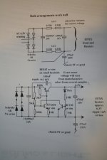
The upper pic (passive cct) has some volts headroom but not for high current stuff. It will get the worst of the worst AC grime off.
Yes connect both it to standard 6.3V AC. Schottky diodes SB550 or sim with low Vf are recommended as low voltage conversion is the least efficient in power terms.
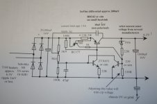
The lower diag is more serious, has typ less than 0.3V diff between in/out and will easily challenge the -60dB ripple rejection of a standard 1A low dropout LM series.
Experimenters and physicists should see the lower dissip & Vin/Vout drop-out advantages of using a pnp as a pass tranny. Ironically most industrial pnp designs get vetoed out.
The only drawback is selection and trimming of the zener to get exact 6.3V DC output and chosen over several makes. A TL431 could also be used here. (Haven't tried this).
Current limiting resistor can be hung on, the Vin/vout diff thus increases to app 0.45V. The jist is enclosed.
There are loads of this type of circuits about... that can be botched up and about..and still work.
:-richj
The upper pic (passive cct) has some volts headroom but not for high current stuff. It will get the worst of the worst AC grime off.
Yes connect both it to standard 6.3V AC. Schottky diodes SB550 or sim with low Vf are recommended as low voltage conversion is the least efficient in power terms.
The lower diag is more serious, has typ less than 0.3V diff between in/out and will easily challenge the -60dB ripple rejection of a standard 1A low dropout LM series.
Experimenters and physicists should see the lower dissip & Vin/Vout drop-out advantages of using a pnp as a pass tranny. Ironically most industrial pnp designs get vetoed out.
The only drawback is selection and trimming of the zener to get exact 6.3V DC output and chosen over several makes. A TL431 could also be used here. (Haven't tried this).
Current limiting resistor can be hung on, the Vin/vout diff thus increases to app 0.45V. The jist is enclosed.
There are loads of this type of circuits about... that can be botched up and about..and still work.
:-richj
Attachments
richj,
cool. The last design you attached that should work with the necessary 5vac to 5vdc for the 300b application I am using correct? I need to do a bit more research but looks straight forward enough.
For the zener selection, how many do you go through normally until you find the good one? What ranges have you seen in this until you find the good zener? Also, the resistors that are not labeled wattage wise, these are 1w correct?
off to do some more reading!
thanx
- Status
- Not open for further replies.
- Home
- Amplifiers
- Tubes / Valves
- Tube heaters AC or DC?