Va= voltage at plate/anode
Vk= Voltage at cathode
Rk = cathode resistor
Ra = anode resistor/load
CRO?
Cathode Ray oscilloscope?
Vk= Voltage at cathode
Rk = cathode resistor
Ra = anode resistor/load
CRO?
Cathode Ray oscilloscope?
Yes! I've seen that abbreviation in many old British electronics books.CRO?
Cathode Ray oscilloscope?
"Cathode ray" is a really old usage, going back to the days before the discovery of the electron by J.J. Thompson in 1897. Back then, scientists knew that some sort of mysterious rays were emitted from the hot cathode (these rays could cast shadows of electrodes inside the tube, and cause fluorescence on the glass bulb), but they had no idea what those rays actually were. So they called them "cathode rays". 🙂
I guess "CRO" will have to be modified to LCO (Liquid Crystal Oscilloscope) these days. Well, it would have to be, if anybody cared any longer. The public isn't interested in such things now, they're too busy swiping endlessly at their phones and watching two-second video clips of cats falling off tabletops. 🙂
-Gnobuddy
Gnobuddy;5495569watching two-second video clips of cats falling off tabletops. :) -Gnobuddy[/QUOTE said:urgent! please give me a link🙄
I'm happy for you, that you found what you were looking for. 🙂~425V...Crisper distortion, more alive feeling, not "hazy" at all...
considerable difference in the distorted tone
I have read similar comments about distortion changes with increasing supply voltage in the past. I just wish I understood exactly why you got the results you did.
Increasing B+ slides the load-line to the right and upwards, and increases the amount of (negative) grid-cathode bias voltage. But I don't know why that should translate into crisper distortion. I wish I did.
-Gnobuddy
Hi fozzy215
Tuning by ear will generally result in getting each stage set for maximum sustain, which is what TUT shows. The interstage attenuators can also be tweaked by ear for the same result in lieu of having a scope or even a meter.
Tuning by ear will generally result in getting each stage set for maximum sustain, which is what TUT shows. The interstage attenuators can also be tweaked by ear for the same result in lieu of having a scope or even a meter.
<fogey>Don't they teach you young whippersnappers anything these days ?</fogey>CRO? I'm unfamiliar with what that is.
🙂🙂😀
OK, I know I'm old but not that old😛"Cathode ray" is a really old usage, going back to the days before the discovery of the electron by J.J. Thompson in 1897
Understand. Can you report the Rk and Ra values? We can all work it out from there.No, didn't document voltages, nor calculate load lines.
Hence the question. It'll be interesting to see where the load line has ended up, particularly compared to the operational areas chart (Marios?) we saw in another thread about a month back.But I don't know why that should translate into crisper distortion. I wish I did.
It suggests that we should abandon the conventional chain-of-RC filters from the screen supply for preamp supply and instead run the preamp straight from the rectifier (or from it's own HV tap), perhaps with some additional filtering.
Understand. Can you report the Rk and Ra values? We can all work it out from there.
V1a: 100k / 1.5k
V1b: 100k / 1.5k
V2a: 330k / 4.7k
V2b: 100k / 1.5k
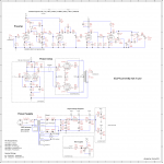
I've attached the schematic of the current state the amp. Keep in mind I'm still prototyping this thing... 😎
Attachments
Thanks for the details. You could always try 220K on plates and 2k2 on cathodes and see if it floats your boat.
Thanks for the details. You could always try 220K on plates and 2k2 on cathodes and see if it floats your boat.
Believe me, I've tried every plate value from 47k - 330k, and cathode values from 470Ω to 100k (lol). And as many combinations at each stage as I had to patience for.
I've settle on 330k/4.7k for the 3rd stage. It gives the right amount of sizzle and sustain I'm looking for. 100k/1.5k balances out the brighter tone.
And the funny thing is, is my ear always seems to gravitate towards a 1.5% cathode-plate ratio, regardless of Ra. Weird.
Last edited:
😎 Thanks.I've attached the schematic of the current state the amp. Keep in mind I'm still prototyping this thing... 😎
Lots of interesting ideas in there - Gnobuddy and I both prefer an eq-distort-eq architecture + different EQ mechanisms so there's a couple of "+1"s there
😎
Narciss-o-quote
guavatone posted this
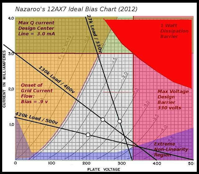
No, this thread.... particularly compared to the operational areas chart (Marios?) we saw in another thread about a month back.
guavatone posted this
Gnobuddy and I both prefer an eq-distort-eq architecture + different EQ mechanisms so there's a couple of "+1"s there
😎
Yea, EQ pre distortion adds so much flexibility.
The post distortion Contour circuit is neat and all, but it really needs a traditional TMB tone stack. I'm limited on front panel space (it's built into a 1U rackmount chassis w/ 8 holes for pots) so I have to make some compromises somewhere.
Thanks for the schematic! It's nice to see something that isn't another exact copy of a design dating from the 1950s. 🙂I've attached the schematic of the current state (of) the amp.
If I may make a suggestion, maybe return C11 to ground rather than to B+. It'll behave exactly the same as far as AC properties of the amp go, because B+ and ground are both signal grounds. But returning C11 to ground will stop it from injecting any noise or hum on the B+ rail directly into the input of V2b.
I think Merlin Blencowe discusses this issue somewhere in his preamp book.
-Gnobuddy
Thanks for the schematic! It's nice to see something that isn't another exact copy of a design dating from the 1950s. 🙂
If I may make a suggestion, maybe return C11 to ground rather than to B+. It'll behave exactly the same as far as AC properties of the amp go, because B+ and ground are both signal grounds. But returning C11 to ground will stop it from injecting any noise or hum on the B+ rail directly into the input of V2b.
I think Merlin Blencowe discusses this issue somewhere in his preamp book.
-Gnobuddy
Oh, I didn't reinvent the wheel; just used bits and pieces from various schematics as a means to an end.
Sure, I'll give it a shot! I need to tweak this circuit anyways. It has absurd amounts of distortion on tap. Not that that is a bad thing per say, but I realized it is prone to squealing if I unplug the guitar and touch the cable. Otherwise it's rather quiet and stable.
EDIT: I just realized as well that there are some typos and whatnot in the schematic. Ex: the control layout doesn't match the some pots/circuits in the schematic. Doesn't really matter, just wanted to point it out.
Last edited:
Another thought - using a much smaller cap across R17 might do the trick too...and no pole-splitting issues to worry about!Sure, I'll give it a shot!
How about clean tones? Are those going to come from one of the currently unused valves (V3, V4)?It has absurd amounts of distortion on tap.
-Gnobuddy
Another thought - using a much smaller cap across R17 might do the trick too...and no pole-splitting issues to worry about!
How about clean tones? Are those going to come from one of the currently unused valves (V3, V4)?
-Gnobuddy
Yea, in a previous version of this preamp I had a 250p across R17, good thinkin! I overlooked that.
Yea, cleans will come from V3. V4 is for a buffed FX loop.
- Status
- Not open for further replies.
- Home
- Live Sound
- Instruments and Amps
- Tube Guitar Preamp - Choosing Supply Voltage?