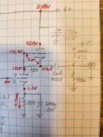
Hi. I came to this unusual circuit topology, can someone explain it to me, what are it features, output impedance, gain, noise, etc...
the cicuit is done using the two sides of the same tube, one top the other.
Tube is the unusual Mullard E180CC
Thanks
the cicuit is done using the two sides of the same tube, one top the other.
Tube is the unusual Mullard E180CC
Thanks
Attachments
Looks like a SRPP to me. From our forum member Merlin
https://www.valvewizard.co.uk/SRPP_Blencowe.pdf
https://www.valvewizard.co.uk/SRPP_Blencowe.pdf

I reckon that's cascode.
The top valve is 'just' a constant current source. Without it , instead just the usual load resistor, the current through the lower valve will be more when the valve is more 'on' when the input signal asks for that and less when it's 'less on'. With that topology the lower valve (both actually) will always operate with the same anode current.
Bit surprising to see a 2 volt drop across a piece of wire at the op of the diagram!
A cascode does indeed have two tubes on top of each other, but besides other differences with SRPP, it has the load resistor between B+ and plate of upper valve. In the drawing the anode of the upper valve is bypassed with a cap.
Again Merlin to the rescue: https://www.valvewizard.co.uk/cascode.html
Again Merlin to the rescue: https://www.valvewizard.co.uk/cascode.html
I learnt it recently in another thread on this forum.I came to this unusual circuit topology, can someone explain it to me, what are it features, output impedance, gain, noise, etc...
the cicuit is done using the two sides of the same tube, one top the other.
In short. It doubles the output current capacity.
It works in push pull. Imagine there is 0 current on the lower part. The top triode gets 0v grid voltage, and all the current will be sunk by the load. The upper portion is far from a current source. You might only get couple times the plate resistance out of it.
Last edited:
Big thanks. No drop of 2V in a wire, voltages changes during warmup and I re-wrote over the initial reading 😉
SB
SB