Good question, Gavin. The topic probably deserves its own new thread.
I'm looking at using a LED/Photocell unit for sensing and control. Check out the Aphex Punch Factory optical compressor. There are opto-isolators that combine the LED and the photoresistor in one package. The photoresistor has a memory that depends on the brightness and duration of the light that has struck it. So they make nice natural compressors. The Aphex unit is excellent for acoustic guitar and vocals, and super simple.
There are a number of schematics out there for compressors. Some seem quite complicated without benefit. Most seem to be a preamp with either a variable grid bias or a variable negative feedback.
Also interested in building this circuit and including it in a tube bass preamp... wondering if it is possible to eliminate the first Cathode follower stage and replace the diode-connected triode for a silicon diode? Would like to get the design down to one tube. If I cant altogether eliminate the cathode follower stage, I will swap it for a MOSFET source follower, but trying to avoid any solid-state devices because I am building on turret board and it is semi-inconvenient to use OpAmps, optocouplers, etc.
Thanks,
Joe
Thanks,
Joe
If you mean the circuit in the first post, I would stay away from it, it's an odd duck and I have searched and never found a reference to anyone who ever got it to work.
You can add a compressor to any preamp with just one tube and some diodes. Basically, you need a variable-mu type tube like an ECC189 or a remote-cutoff pentode (it can be strapped as a triode), then either a tube diode such as a 6AL5 or for solid state, small signal such as 1N4148.
You can add a compressor to any preamp with just one tube and some diodes. Basically, you need a variable-mu type tube like an ECC189 or a remote-cutoff pentode (it can be strapped as a triode), then either a tube diode such as a 6AL5 or for solid state, small signal such as 1N4148.
i mean it doesn t work correctly 😛 ...
it s a very loud sawtooth or square wave around 80/100 hz ( i m not sure bout the wave and freq , i don have a scope ) comin out of it , but when i turn the 2nd pot (25k) all the way down the noise become silence suddenly , i connected my signal generator to it , very very little pulsin sound come out of it !!!
the schematic is wrong..i know why..
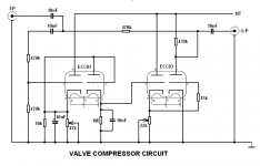
The grid of the second triode must be conected with the anode to form a diode ,and most importantly the 10uf capacitor in not in series there,it goes like this : The 10uf capacitor is in parallel with the two 10k resistors and all 3 are conected between the cathode and the ground of the first triode (this forms the first time constant).The cathode of the FIRST triode is conected with the anode and the grid of the SECOND triode.The cathode of the SECOND triode is conected in parallel with a 1Mohm RESISTOR,NOT POTENTIOMETER*,and the 0.01 uf capacitor (this forms the second time constant).The first potentiometer in placed instead of one of the two 10k resistors in the first triode and it should be around 47k .In rest the schematic is ok.If you make this changes ,you will have 100% fine working compressor ...salutations from Romania 😉
It is corect...you have 100 guarantee of a working compressor ..with the first pot you change the frequency rate,and with the second pot you change the compression level...good luck 😉Hopefully I have redrawn the circuit correctly with those changes incorporated.
How come the first triode isn't destroyed when the pot grounds its cathode?
And the third triode as well - nasty! 😱
And the third triode as well - nasty! 😱
you never sow direct coupled triodes? :| .they work as a rectifier in circuit..they don't amplify...i'm using the compressor 2 mounths from now and i don't have any problems with tube exploding or such..Just do this schematic the way i presented an we will talk later 😉 have fun! Bob from Romania
you never sow direct coupled triodes? :| .they work as a rectifier in circuit..they don't amplify..
Yes, I've seen direct connected valves, and plenty of valve rectifiers (the second triode is the one wired as a rectifier).
But that's not the major problem - if the pots are turned to minimum resistance then the first and third triodes are then connected directly across the full supply, anode directly to full HT and cathode directly to chassis. As there's no bias (other than the now removed cathode bias) the valves are likely to destroy themselves.
Presumably there should be an extra resistor in series with the pots to prevent this?.
if you put a resistor in series with the pot ,you will loose the frequency response.best way is to put a "tampon"resistor or a resistor voltage divider at the HT ,so that the courent is absorbed by the tampon resistor
...what about hi Z out ?
It is not a rule that tubes must be biased ,it depends on the aplication they are used.They have large plate resistance ,so at they'r working voltage ,direct coupling is not a problem.In this circuit the first 3 triodes serves as rectifiers ,and the last one as variable resistance.The first triode charges with dc courent from the kathode the 10uf capacitor with the voltage desired by the value of the first pot seted.This forms the first time constant .The dc courent goes through the second rectifier wich is the diode made from the second triode who has the 0.01 capacitor and the 1mohm resistor.This forms the second time constant.The third triode is also rectified by the whole chain and gives variable dc voltage by the change of the second pot to the forth triode used as a variable resistor.So everything is DC in this circuit.The whole compressor idea is to put the signal amplitude near to the gnd at different speads ,so that all peak levels goes at the same level. I'm romanian,sorry for the english.You will need a preamp before and after this compressor circuit
Last edited:
Unfortunately, tubes only conduct in one direction. This means the fourth tube has to be biased so its plate is at a positive voltage otherwise the negative half cyle of the input waveform would not be affected. This means the tube will amplify the changing dc voltage on its grid. This will appear as a thump at the output unless the LF response is not severely reduced. This is fine for a speech compressor, which is what the original circuit was designed for, but it is no good for a bass guitar compressor.
Cheers
Ian
Cheers
Ian
In this circuit the first 3 triodes serves as rectifiers ,and the last one as variable resistance.The first triode charges with dc courent from the kathode the 10uf capacitor with the voltage desired by the value of the first pot seted.
I would say the first and third triodes are cathode followers, only the second is a rectifier - but it's an incredibly poorly conceived and designed circuit.
And the pot's certainly require series resistors for a practical circuit - no idea what you mean by 'tampon' in this context, presumably it's a language problem?.
this is the single tube version of the compressor with the equivalent circuit..read the whole page... https://www.google.ro/search?q=dire....preservationsound.com%2F%3Fp%3D628;4330;6160
Why not simply use the first valve as a cathode followed, rectified by the second triode wired as a diode, with the attack/decay components after that rectifier?.
The pots in that article also require series resistors to prevent damage, I realise the pots are only used to set the gain levels, and not user adjustable, but that's no excuse to have a pot which can be adjusted to stop the device working, and to cause damage.
Just because a design is published in a magazine, doesn't mean it's any good 😀
Personally I can't see any point in even wanting to use a valve compressor, when far higher quality designs are easily available.
Why not simply use the first valve as a cathode followed, rectified by the second triode wired as a diode, with the attack/decay components after that rectifier?.
The pots in that article also require series resistors to prevent damage, I realise the pots are only used to set the gain levels, and not user adjustable, but that's no excuse to have a pot which can be adjusted to stop the device working, and to cause damage.
Just because a design is published in a magazine, doesn't mean it's any good 😀
Personally I can't see any point in even wanting to use a valve compressor, when far higher quality designs are easily available.
well it's your choise to make this tube compressor or not ,the main idea is that it works the way it is..i'm using it for about 2 mounths in my amplifier and no damage causing.And by the way either the single or the double tube versions don't use series resistor with the pots and the cathode of the tube...I don't see it good luck 😉
- Status
- Not open for further replies.
- Home
- Live Sound
- Instruments and Amps
- Tube Compressor