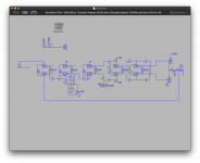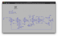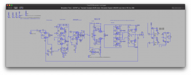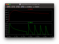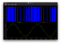
So after a lot of soul searching and going around in circles I finally decided to bite the bullet in a sense in creating a tube based Analogue to DSD amp. This follows the plan with the SMPS with the power being an isolated switching of the DSD output to give the final audio.
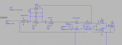
I've started with the basics that I'm currently building out by creating simple first order logical analogue to digital DSD converter.
These building blocks are relatively simple to then map into a valve topology.
U2 - difference - this will simply be a differential amp using two triodes.
U1 - integrator - this will again can be two triodes.
U4 - the comparator - this can be.. you guessed two triodes.
D-latch = this can be done with OR-NOT and so 5 triodes.
At this point the output is DSD and so simply I need a gate driver, or simply a push-pull set of tubes (replacing SW2 and SW3). These simply have to be able to produce ON or OFF so they don't need to be very linear.
I still have some more work todo on the logic before I jump into the tube implementation. Specifically making the system biased to operate in 'class A' so it will be tube compatible.
There are some 'additions' in terms of functionality I could do such as make U2 the front end amplification, even making the input differential..
Looking at the different VHF capable tubes (ie 30MHz), there's a number out there. Linearity-wise, past the integrator the linearity isn't such a problem.
So it's possible to tailor the valves in use - ECC88, E88CC, 6BQ7A, even the 'odds' such as sharp cutoff 6AK5, 6ZH1P etc could be used. The nice thing is that you don't need 'audio' valves. The lower the Miller capacitance tubes the better as we to keep up with the switching speed.. If we want fast DSD that, unfortunately means, RF tubes rather than audio.
The main drive tubes on the output are pretty much anything that can switch between two voltages fast. Unless - you make the driver stage fast that then drives the final output stage through the LPF resulting in analogue drive for the output.
I've already tried a ecc99 version of this in ltspice, mainly to test out the ideas of the different tube amp stages for each logic component. However my gut feeling is old fave ecc99 simply isn't suited for the high speed switching. So I am eyeing up the 6BQ7A given it's 1/2 the price of ecc88/e88cc. Now I may switch to pentodes if I can optimise the design after it's working but for now - triodes make it easier from a mental perspective.
Hmm phasing is a real PITA. I was going to attempt to keep them all at the same voltage but of course, tubes and caps change the phase.
Last edited:
For those wondering what DSD means Direct Stream Digital - Wikipedia
Analogue line source -> 1-bit sigma delta ADC -> 1-bit DSD digltal at 9MHz (currently) -> a push pull digital output -> low pass filter -> analogue output.
To get down to a low impedance to drive a speaker, you still need an audio band output xfmr.
It would be much more attractive if it used RF Buck stages to get high current output with tiny ferrite xfmrs..
It would be much more attractive if it used RF Buck stages to get high current output with tiny ferrite xfmrs..
Last edited:
To get down to a low impedance to drive a speaker, you still need an audio band output xfmr.
It would be much more attractive if it used RF Buck stages to get high current output with tiny ferrite xfmrs..
That is precisely where this is headed 😀 it will need a gate driver for the power mosfet and this will connect to the DC link as discused in the tube modulated smps.
I’d already looked at coilcraft coupled inductors, they do 1:1 and 1:N.
Just for now with the switching output I’ve put a simple PP output to get the circuit up and running.
Actually - it doesn't matter where the DC comes from - it could be a 5V/12V/24V/48V.. 150W/../4KW SMPS that's then switched, as long as the DC to output switching stage is capable of keeping up and the required drivers are used. There's also finding the right inductors etc that starts becoming esoteric. Smaller switching is easier - a Walmart 5V 1A SMPS brick could easily work as an initial test setup - although the output noise may be higher. I have a SMPS 5A 2-15V adjustable brick and a 13.8V 5A continuous linear supply that I could use as simple test setup.
What I do want is that the output is isolated from the mains. Ideally I'm looking at a PFC boost, then isolated switching. However at MHz the output stages, bar the filtration, are likely to be very small!
From previous research finding a KHz inductor for step down N:1 is not easy. Most switching ICs for step down are MHz direct current chopping. So with this switching being MHz and a 1:1 power inductor could then provide isolation into 1500V for example.
The nutty alternative to an output audio transformer to help impedance is paralleled tubes but given the 20mA max of the lower voltage RF tubes.. that's going make one large digital OTL. Hence thinking of SS final switching for speak out except for example for the headphone jack. The same output section can then be used for DSD streaming from digital players etc. That is the plan..
Just to add ltspice - well it ran overnight and managed about 24ms at DSD512 rates. So this is going to be slow - I still need to fix some issues so the circuit isn't functional. I just wanted to see how the voltages settled.
Last edited:
I made a boo-boo in scribbling down the logic gates with lines not straight enough for an AND gate which carried over to the tube design - now corrected.
3.16V input 10kHz sine wave, pushing about 20W out (hence the PP stage valves are out of spec).
WIP but I have the first FFT for about 40ms of run time. The audio output is pushing 200V but ignore that, it's simply I've got around to really correcting the output stage.
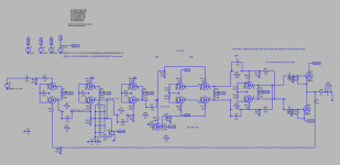
Output audio
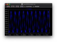
FFT 40ms of run time, longer and I'd expect the noise floor to drop.
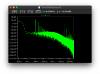
Zoom into the audio area:
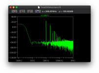
Now I can settle down and tune the system, I'm thinking of putting mosfet output switches on and a PFC just to make a full amp. I'm not entirely convinced the system is functioning correctly - I need to set aside a couple of hours to methodically work through the wave forms from a longer run.
I've also been looking at VHF pentodes. I'm trying to target valves that aren't NOS so in the end the e88cc/ecc88 may still be the better choice for anyone considering this.
3.16V input 10kHz sine wave, pushing about 20W out (hence the PP stage valves are out of spec).
WIP but I have the first FFT for about 40ms of run time. The audio output is pushing 200V but ignore that, it's simply I've got around to really correcting the output stage.

Output audio

FFT 40ms of run time, longer and I'd expect the noise floor to drop.

Zoom into the audio area:

Now I can settle down and tune the system, I'm thinking of putting mosfet output switches on and a PFC just to make a full amp. I'm not entirely convinced the system is functioning correctly - I need to set aside a couple of hours to methodically work through the wave forms from a longer run.
I've also been looking at VHF pentodes. I'm trying to target valves that aren't NOS so in the end the e88cc/ecc88 may still be the better choice for anyone considering this.
Last edited:
To get down to a low impedance to drive a speaker, you still need an audio band output xfmr.
It would be much more attractive if it used RF Buck stages to get high current output with tiny ferrite xfmrs..
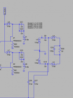
Initial stab at a Cuk isolated output stage using small (but not correctly sized) coupled inductors. I'll look at some RF inductors and model the parameters correctly, however the main issue atm is getting the MOSFET drive right. I will add a current sense limiter too but that's added complexity atm.
I'm currently chewing through the frontend (diff/integrator/comparator). However I've also been researching other valves that would also perform in modulator at 30-40Mhz are:
6C4 / EC90 - 150Mhz capable
6AB4/ECC92 - VHF
12AT7/ECC81 - two 6AB4/ECC92 in one and can do VHF unlike the 12AU7
ECC84 - mu 24
ECF80 - mu 20 220MHz capable
6AK5 - 100Mhz
Odd tubes that will not work:
12AU7 / ECC82 - although these are two 6C4/EC90, and the capacitances are low they supposedly top out at 30kHz
ECL80 - note that this capable but tap the tube and the clocks will go nuts.
EF50 - this could work but it's only reliable up to 30MHz supposedly
E88CC
More tubes on my list to investigate are:
ECH81 (30Mhz)
6H30 - I thought this was a 12BH7 alternative so this may be a audio valve (note I see it has 6pF capacitances so I suspect it's not likely to work).
ECH81
6BG6
6J6/ECC91 (CV858) - I think this is would work
6AG5
6SN7 - I've seen this being reportedly used for oscillators.. but hmm.
Acorn 954 - esoteric ...
Last edited:
So there's a number of ways to create some of these pieces - miller integrator etc but all have their own little gotchas.
So one building block is the tube op-amp. Now there's lots of versions of this out there but underlying this are the principles:
* high input impedence (draws no current)
* low output impedance (allow as much current as needed)
* 0V centre point for input & output
* infinite open-loop amplification (high mu)
So with that I've taken the standard op-amp design from 1962 - it uses a differential amp to provide the difference, then amplifies this to provide a low impedance output. Note the split cathode on the upper pair.The old system used a pair of 12AX7 which has a mu of 100 which gives the high voltage swings given very little input current. Only issue is 12AX7 is about 4Vpp at 300V or 3Vpp for 200V. Also having this be able to sit at ±150-200V would be useful as it could be possible to squeeze it into 390V without too much problem (the B+ below shows 350 but it's actually 200).
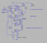
This is 90% there, and it will be a useful building block. The issues with this design are (a) output is low - that's down to the output stage needing some bias balancing, (b) the gain is lower than perhaps it should be and the final (c) high frequency performance (a high frequency sine wave is good but need test with square wave. More than enough for the purpose though - there's a balance of voltage and current for this..
I've stuck with the 6BQ7As for now for the model, but these have a mu of 39 which is a little low. So the next step is finding a higher mu that allows around 6Vpp with a higher mu but has low capacitances so it can carry signals 30Mhz+ without acting as a low pass filter. Oh.. and doesn't break the bank.
So I've selected the old EF90 as the pentode - this is good under 200Mhz as this simplifies the AND gate.
Other valves in the list above:
ECH81 - nope.
6H30 - hell no.
ECH81 - it could but it's a pentode (5-8pF and triode 1-2pF).. so no
6AG5 - yes 400Mhz
6AK6 - yes given it's capacitances 3-4pF it could do with a little lower capacitances.
6J6 - yes 1-2pF capacitances.
6SN7GT - yes, in theory with 3-4pF it may work.. but better check
E88CC - yes.
So one building block is the tube op-amp. Now there's lots of versions of this out there but underlying this are the principles:
* high input impedence (draws no current)
* low output impedance (allow as much current as needed)
* 0V centre point for input & output
* infinite open-loop amplification (high mu)
So with that I've taken the standard op-amp design from 1962 - it uses a differential amp to provide the difference, then amplifies this to provide a low impedance output. Note the split cathode on the upper pair.The old system used a pair of 12AX7 which has a mu of 100 which gives the high voltage swings given very little input current. Only issue is 12AX7 is about 4Vpp at 300V or 3Vpp for 200V. Also having this be able to sit at ±150-200V would be useful as it could be possible to squeeze it into 390V without too much problem (the B+ below shows 350 but it's actually 200).

This is 90% there, and it will be a useful building block. The issues with this design are (a) output is low - that's down to the output stage needing some bias balancing, (b) the gain is lower than perhaps it should be and the final (c) high frequency performance (a high frequency sine wave is good but need test with square wave. More than enough for the purpose though - there's a balance of voltage and current for this..
I've stuck with the 6BQ7As for now for the model, but these have a mu of 39 which is a little low. So the next step is finding a higher mu that allows around 6Vpp with a higher mu but has low capacitances so it can carry signals 30Mhz+ without acting as a low pass filter. Oh.. and doesn't break the bank.
So I've selected the old EF90 as the pentode - this is good under 200Mhz as this simplifies the AND gate.
Other valves in the list above:
ECH81 - nope.
6H30 - hell no.
ECH81 - it could but it's a pentode (5-8pF and triode 1-2pF).. so no
6AG5 - yes 400Mhz
6AK6 - yes given it's capacitances 3-4pF it could do with a little lower capacitances.
6J6 - yes 1-2pF capacitances.
6SN7GT - yes, in theory with 3-4pF it may work.. but better check
E88CC - yes.
Last edited:
Time for a Duval beer I think. Not had a beer for ages and it's a public holiday 3 day weekend here in the UK..
Current mess, I mean state.
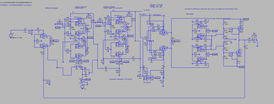
I still need to tune more.. but it's far better than it was this morning.
10.5 tubes per channel (B7A and B9A), but I want to swap out the U2/U3 for a M40 cascode and driver (4 tubes per channel) but I will add a second order to it. If I don't optimise the building blocks anything that's: 4 tubes per differential, two per integrator, two per comparator and then 4.5 for the D-latch then the final output (currently U12/U13) but for now that is likely to be 1 tube as a little driver. 20 tubes per channel..
It is possible to short cut some of these using diode logic and use a simple single tube miller tube comparator etc but I want to have the 1st order version working first with direct op-amp style tube configuration.
In the final thing - I will probably make a merged M40-esque second order differential integrator - that should reduce the number of tubes. Replacing the output driver with solid state to perform the final MOSFET driver and then driving would then be the final point. Add GAN if you want but for me this will be something simpler I think.
Current mess, I mean state.

I still need to tune more.. but it's far better than it was this morning.
10.5 tubes per channel (B7A and B9A), but I want to swap out the U2/U3 for a M40 cascode and driver (4 tubes per channel) but I will add a second order to it. If I don't optimise the building blocks anything that's: 4 tubes per differential, two per integrator, two per comparator and then 4.5 for the D-latch then the final output (currently U12/U13) but for now that is likely to be 1 tube as a little driver. 20 tubes per channel..
It is possible to short cut some of these using diode logic and use a simple single tube miller tube comparator etc but I want to have the 1st order version working first with direct op-amp style tube configuration.
In the final thing - I will probably make a merged M40-esque second order differential integrator - that should reduce the number of tubes. Replacing the output driver with solid state to perform the final MOSFET driver and then driving would then be the final point. Add GAN if you want but for me this will be something simpler I think.
Last edited:
Signs of life..
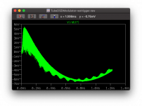
I still need to trouble shoot the op amps, but I suspect once that's done (given they're both identical) the resulting output should be more promising.
I also had a look into solid state RF output switches. There's a couple of boundaries - 20V, 48V, 175V and then we're into the 400V+ bracket. Some nice little 8W 2Ghz capable transistors for low impedance, and then 150W+ transistors that are capable before we start in the big power GAN. Lots of 500kHz switches which would be unsuitable.
It's interesting - when you run a 100Hz signal through the opamp (12AT7 model) I can get a 3.16V peak to output as 38Vpp 6mA. Switch up to 100Mhz and the model starts sucking current. The real tube is good for 300Mhz.
- Home
- Amplifiers
- Tubes / Valves
- Tube Analogue to DSD Modulator.
