Hehe. It occurred to me last night whilst watching TV with the mrs that I had some logic errors - first the AND gate was setup as a NAND and the base of the NOR gate was incorrect too.
I got down to the bottom of the oscillation - that's the opamp, in the case of the comparator the feedback was too large. What concerns me is that the oscillations are 200Khz.. which makes me think that there's some bandwidth work needed.
Starting to see some life - top is the oscillation on the output. Mid and bottom is the comparator - detecting the up and down of the difference of the sine wave.

WIP..
I got down to the bottom of the oscillation - that's the opamp, in the case of the comparator the feedback was too large. What concerns me is that the oscillations are 200Khz.. which makes me think that there's some bandwidth work needed.
Starting to see some life - top is the oscillation on the output. Mid and bottom is the comparator - detecting the up and down of the difference of the sine wave.
WIP..
trace 1 - input (10Khz)
trace 2 - integrator
trace 3 - comparator
trace 4 - output switching

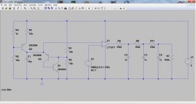
Current circuit:

The comparator and dlath etc needs some work.. starting to look promising.
trace 2 - integrator
trace 3 - comparator
trace 4 - output switching
Current circuit:
The comparator and dlath etc needs some work.. starting to look promising.
Well, I can hardly follow your project so my post may be irrelevant but FWIW here it is...
Some time ago I tried to design a 1-bit ADC based on a comparator. It supposed to sample the analog signal using a sawtooth for reference voltage. The output is PWM alike and then it is reconstructed with LPF. As is it's not refined and phase shift seems proportional to frequency. Just hopping to be inspiring...
Some time ago I tried to design a 1-bit ADC based on a comparator. It supposed to sample the analog signal using a sawtooth for reference voltage. The output is PWM alike and then it is reconstructed with LPF. As is it's not refined and phase shift seems proportional to frequency. Just hopping to be inspiring...
Attachments
To get down to a low impedance to drive a speaker, you still need an audio band output xfmr.
It would be much more attractive if it used RF Buck stages to get high current output with tiny ferrite xfmrs..
Well, I can hardly follow your project so my post may be irrelevant but FWIW here it is...
Some time ago I tried to design a 1-bit ADC based on a comparator. It supposed to sample the analog signal using a sawtooth for reference voltage. The output is PWM alike and then it is reconstructed with LPF. As is it's not refined and phase shift seems proportional to frequency. Just hopping to be inspiring...
Yup this is following the normal 1 bit sigma delta conversion. The main issue I have is the opamp piece at the moment. That I need to get down and do a bode plot and sort out the oscillation that appears at about 200Khz.
https://www.analog.com/media/en/technical-documentation/application-notes/an148fa.pdf
https://www.edn.com/one-extra-resistor-fights-ic-op-amp-oscillations/
Sawtooth works for PWM. I've used that on the model for the power supply PFC. It nicely provides the intersection for the side wave that gives the with of the pulse required. pulse density is slightly different - the pulses are the same with but they can be latched on and off.
I had the initial model working with ideal behavioural gates etc that's fine. This is more difficult as I've created an opamps using tubes.
The feedback loop is tooooo long... my guess...
Certainly a possibility. The oscillation is reproducible with no input or output load with just a single op amp. So at least I can work though it.
Looking at the bode plots for a single valve and the ltspice .ac command, it shows a steep roll off after about 1Mhz. I can tune the opamp to work better at 1-30Mhz at the detriment of the audio spectrum. Hmm.
This has some interesting observations for VHF and tubes: https://worldradiohistory.com/BOOKSHELF-ARH/Handbooks/Radio-Handbook-14-1956.pdf (section 4-6).
This has some interesting observations for VHF and tubes: https://worldradiohistory.com/BOOKSHELF-ARH/Handbooks/Radio-Handbook-14-1956.pdf (section 4-6).
Last edited:
PC 900, Tube PC900; Rohre PC 900 ID3451, Triode, vacuum
PC900 @ The Valve Museum
PC97 @ The Valve Museum
The PC97 is a frame grid triode that in addition to a very high mutual conductance of 13.00 mA/V has an unusually low grid to anode capacitance of about 0.5 pF
PC900 @ The Valve Museum
PC97 @ The Valve Museum
The PC97 is a frame grid triode that in addition to a very high mutual conductance of 13.00 mA/V has an unusually low grid to anode capacitance of about 0.5 pF
Last edited:
Both would work. Typically the reason that the KW2 used 12AX7s is the 100mu.
6c45pi - that would work 56mu, although the cap is a little high. Tube price is a little high (£28)
PC97 - that would work, 65mu would be a better fit for this. (£9 - single triode)
PC900 - 84mu - nice. (£7.50 - single triode).
One thing did occur to me during the night - the test gear (ie uTracer etc) used to create the models may not test with 40Mhz. Also I will look at power RF filtering for the op amp model.
Some good possible options there!
Wont be much movement today - have the wedding anniversary dinner.
It's occurred to me that the problem could be solved using a 3rd pair of triodes for cascodes or use a folded BJT cascode. That tames the miller capacitance and reduces the impact on the bandwidth.
During the testing I noticed that the bode plots for the anode being constrained and the cathode having far more bandwidth. So this would solve the issue or vastly improve in two ways:
a) reduce/no need for capacitors - this reducing the capacitance driven from the differnential amp anode and amplifications stages (this means less resistance and so the frequency cut off should increase).
b) should improve the bandwidth of the tubes themselves.
- Home
- Amplifiers
- Tubes / Valves
- Tube Analogue to DSD Modulator.