Can't say. You have not given any clues of what you built or how it is wired. No drawings, no schematic, no photos.Couldn't there be something that I'm missing in stereo tube amps circuitry?
There is likely more than one mistake in wiring.
Lifted ground will eliminate voices if they are in the middle, as only the difference between channels gets amplified.
Lifted ground will eliminate voices if they are in the middle, as only the difference between channels gets amplified.
More than likely its just the stupid jack. 3 and 4 wire 1/8” jacks are not compatible with each other. My headset came with a Y-adapter jack, one 4-wire jack to one 3 wire plug (for phones out) and one 2-wire plug (for mic input). Plugs into the one jack on the laptop, two jacks on the front (or sound card) on a desktop using the adapter. I’m sure they make them going the other way too.

I would try a different source and see if the amp functions properly. An ordinary 1/8” stereo plug should function properly in pretty much any phone that is working correctly. I have never had problems simply plugging in a 1/8” stereo plug to the phone headphone jack, with the other ends of the cable having RCA plugs that go into my stereo.
So after a week, I found the problem. I can't really tell why that caused the issue, but now, it works.
That's easy to check with another source like a CD player. If that's OK, your amp is OK.Couldn't there be something that I'm missing in stereo tube amps circuitry?
Post # 10 has the likely answer.
Jan
I second this statement. Do/did you also observe missing bass response? In addition to lead voices low frequencies also use to be centered during mastering.
Best regards!
Best regards!
So what than was the problem?So after a week, I found the problem. I can't really tell why that caused the issue, but now, it works.
You can get no voices if the input ground or the speaker grounds come off. You then get L-R in one speaker and R-L in the other. If you connect a single speaker between the L output and R output and ignore the grounds you get the same result.
In post #25 TS wrote that he found 'the problem', but that he doesn't know how it caused the issue of 'no voices'.
Why doesn't TS let us know what "the problem" was?
Why doesn't TS let us know what "the problem" was?
In post #25 TS wrote that he found 'the problem', but that he doesn't know how it caused the issue of 'no voices'.
He was listening to an instrumental version?
Hi guys! I'm once again writing on this thread. I solved the problem with low vocals with swapping R7 and R10 at one channel. Yes I had to accept that one channel is a bit lower volume but the amp still sounds fantastic. But I still can't figure out why this helped. All grounds and connections checked multiple times. The included schema is one channel preamp section. The it goes to the single 6550 output stage.

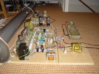
Well I still have it just on the table not in the chasis so it is just a bunch of wires, kinda messy
OK, but post some pictures of your build anyway if you really want to be helped.
And what about some measured voltages?
And what about some measured voltages?
I see an o'scope. Have you checked the polarity of your outputs on the scope? Using a sawtooth waveform makes it easy to see.
That's the first place I would look and it's an easy sanity check.
That's the first place I would look and it's an easy sanity check.
Thanks. Can you provide us with the cathode and anode voltages of the three stages?
Some remarks:
Your build reminds me of my go at a guitar amp with reverb. It did work but not very well (noisy, not enough reverb), At the time (2007) I just rediscovered this hobby after having lost interest in it when I still was a kid, still being blissfully unaware of stray capacitances caused by long leads to the tube sockets.
Some remarks:
- The datasheets for the 6550 state as maximum value for the grid leak resistor 250K when using cathode bias, and 50K when using fixed bias. The value in your schematis is 1M, so way too high. This could lead to damage.
- Eventhough there are some potential dividers between the three stages, the total gain of the three stages is very high. Why creating so much gain, while just partly waisting it again in potential dividers (which act like fixed volume pots)?
- Where is the 'real' volume pot?
- The values of the cathode resistors in your schematic are unusually high (4K7, 6K8 and 10K).
- With R3 not having a capacitor parallel to it, it's better to connect C2 to the cathode instead of ground.
Your build reminds me of my go at a guitar amp with reverb. It did work but not very well (noisy, not enough reverb), At the time (2007) I just rediscovered this hobby after having lost interest in it when I still was a kid, still being blissfully unaware of stray capacitances caused by long leads to the tube sockets.
Attachments
Ok, so the Anode 1 = 192.5V Cathode 1 = 3,67V Anode 2 = 186,7V Cathode 2 = 2,43V Anode 3 = 179,8V Cathode 3 = 10,4V and Cathode 4 = 29V. I chanded the grid leak from 1M to 120K as you sad and the voices aren't already that low. Thanks
- Home
- Amplifiers
- Tubes / Valves
- Tube amp - no voices problem