Hello, I've got some 2E22's and want to try run them in triode. Any idea if G3 can be connected to plate (100R), similar to G2. Something like 'right-handed-triode'.
This tube is a dht pentode 😀...why are you making it a triode? Enjoy the pentode mode. I've made it a few times and it's great.
Here are some measurements of 2E22 in triode mode
G2 G3 connected to Anode.
.
I made spice 2 models, same but one for DHT, other standard.
Maybe it could help to establish needed and optimal settings?
.

these settings could be use for fain stage input with 4Vp-p. (Not for Amplifier...)

G2 G3 connected to Anode.
.
I made spice 2 models, same but one for DHT, other standard.
Maybe it could help to establish needed and optimal settings?
.
these settings could be use for fain stage input with 4Vp-p. (Not for Amplifier...)
Code:
****  Composite DHT *****************************************
* Created on 01/16/2025 17:49 using paint_kit.jar 3.1
* www.dmitrynizh.com/tubeparams_image.htm
* Plate Curves image file:
* Data source link: 2E22 triode mode measurements DIY audio site
* Vf=6.3V If=1.5A Pa=30W PG2=10W
* Capacitances in triode mode are estimated
* A+G2+G3
*----------------------------------------------------------------------------------
.SUBCKT 2E22_DHT 1 2 3 4 ; P G K1 K2
+ PARAMS: CCG=13.7P  CGP=9.7P CCP=8.7P RFIL=4.2
+ MU=8.874 KG1=1395 KP=64 KVB=300 VCT=-2.85 EX=1.412 RGI=2000
*----------------------------------------------------------------------------------
* Vp_MAX=600 Ip_MAX=140 Vg_step=5 Vg_start=5 Vg_count=14
* Rp=4200 Vg_ac=0.25 P_max=40 Vg_qui=-11 Vp_qui=247
* X_MIN=51 Y_MIN=119 X_SIZE=922 Y_SIZE=443 FSZ_X=1763 FSZ_Y=690 XYGrid=true
* showLoadLine=y showIp=y isDHT=y isPP=n isAsymPP=n showDissipLimit=y
* showIg1=n gridLevel2=n isInputSnapped=n
* XYProjections=y harmonicPlot=y dissipPlot=y
*----------------------------------------------------------------------------------
RFIL_LEFT    3  31 {RFIL/4}
RFIL_RIGHT   4  41 {RFIL/4}
RFIL_MIDDLE1 31 34 {RFIL/4}
RFIL_MIDDLE2 34 41 {RFIL/4}
E11 32 0  VALUE={V(1,31)/KP*LOG(1+EXP(KP*(1/MU+V(2,31)/SQRT(KVB+V(1,31)*V(1,31)))))}
E12 42 0  VALUE={V(1,41)/KP*LOG(1+EXP(KP*(1/MU+V(2,41)/SQRT(KVB+V(1,41)*V(1,41)))))}
RE11 32 0 1G
RE12 42 0 1G
G11 1 31 VALUE={(PWR(V(32),EX)+PWRS(V(32),EX))/(2*KG1)}
G12 1 41 VALUE={(PWR(V(42),EX)+PWRS(V(42),EX))/(2*KG1)}
RCP1 1 34 1G
C1 2 34 {CCG} ; CATHODE-GRID
C2 2 1 {CGP} ; GRID=PLATE
C3 1 34 {CCP} ; CATHODE-PLATE
D3 5 3 DX ; FOR GRID CURRENT
D4 6 4 DX ; FOR GRID CURRENT
RG1 2 5 {2*RGI} ; FOR GRID CURRENT
RG2 2 6 {2*RGI} ; FOR GRID CURRENT
.MODEL DX D(IS=1N RS=1 CJO=10PF TT=1N)
.ENDS 2E22_DHT
*$


****  ******************************************
* Created on 01/16/2025 17:50 using paint_kit.jar 3.1
* www.dmitrynizh.com/tubeparams_image.htm
* Plate Curves image file:
* Data source link: 2E22 triode mode measurements DIY audio site
* Vf=6.3V If=1.5A Pa=30W PG2=10W
* Capacitances in triode mode are estimated
* A+G2+G3
*----------------------------------------------------------------------------------
.SUBCKT 2E22_triode 1 2 3 ; Plate Grid Cathode
+ PARAMS: CCG=13.7P  CGP=9.7P CCP=8.7P RGI=2000
+ MU=8.874 KG1=1395 KP=64 KVB=300 VCT=-2.85 EX=1.412
*----------------------------------------------------------------------------------
* Vp_MAX=600 Ip_MAX=140 Vg_step=5 Vg_start=5 Vg_count=14
* Rp=4200 Vg_ac=0.25 P_max=40 Vg_qui=-11 Vp_qui=247
* X_MIN=51 Y_MIN=119 X_SIZE=922 Y_SIZE=443 FSZ_X=1763 FSZ_Y=690 XYGrid=true
* showLoadLine=y showIp=y isDHT=n isPP=n isAsymPP=n showDissipLimit=y
* showIg1=n gridLevel2=n isInputSnapped=n
* XYProjections=y harmonicPlot=y dissipPlot=y
*----------------------------------------------------------------------------------
E1 7 0 VALUE={V(1,3)/KP*LOG(1+EXP(KP*(1/MU+(VCT+V(2,3))/SQRT(KVB+V(1,3)*V(1,3)))))}
RE1 7 0 1G  ; TO AVOID FLOATING NODES
G1 1 3 VALUE={(PWR(V(7),EX)+PWRS(V(7),EX))/KG1}
RCP 1 3 1G   ; TO AVOID FLOATING NODES
C1 2 3 {CCG} ; CATHODE-GRID
C2 2 1 {CGP} ; GRID=PLATE
C3 1 3 {CCP} ; CATHODE-PLATE
D3 5 3 DX ; POSITIVE GRID CURRENT
R1 2 5 {RGI} ; POSITIVE GRID CURRENT
.MODEL DX D(IS=1N RS=1 CJO=10PF TT=1N)
.ENDS 2E22_triode
*$
Attachments

Hooman, thanks for the encouragement 😀. I'm building it on a Tubelab board, switchable Pentade /Triode.This tube is a dht pentode 😀...why are you making it a triode? Enjoy the pentode mode. I've made it a few times and it's great.
Recently built a GU50 (SSE), with G2 & G3 strapped to the anode and it sounded WOW (Softone RW--20 OPT). So, I thought lets give the 307a & 2e22 a shot.
Thank you Zoran. This will be very helpful 🙂👍Here are some measurements of 2E22 in triode mode
G2 G3 connected to Anode.
.
I made spice 2 models, same but one for DHT, other standard.
Maybe it could help to establish needed and optimal settings?
.
View attachment 1442142
these settings could be use for fain stage input with 4Vp-p. (Not for Amplifier...)
View attachment 1442144
Code:**** Composite DHT ***************************************** * Created on 01/16/2025 17:49 using paint_kit.jar 3.1 * www.dmitrynizh.com/tubeparams_image.htm * Plate Curves image file: * Data source link: 2E22 triode mode measurements DIY audio site * Vf=6.3V If=1.5A Pa=30W PG2=10W * Capacitances in triode mode are estimated * A+G2+G3 *---------------------------------------------------------------------------------- .SUBCKT 2E22_DHT 1 2 3 4 ; P G K1 K2 + PARAMS: CCG=13.7P CGP=9.7P CCP=8.7P RFIL=4.2 + MU=8.874 KG1=1395 KP=64 KVB=300 VCT=-2.85 EX=1.412 RGI=2000 *---------------------------------------------------------------------------------- * Vp_MAX=600 Ip_MAX=140 Vg_step=5 Vg_start=5 Vg_count=14 * Rp=4200 Vg_ac=0.25 P_max=40 Vg_qui=-11 Vp_qui=247 * X_MIN=51 Y_MIN=119 X_SIZE=922 Y_SIZE=443 FSZ_X=1763 FSZ_Y=690 XYGrid=true * showLoadLine=y showIp=y isDHT=y isPP=n isAsymPP=n showDissipLimit=y * showIg1=n gridLevel2=n isInputSnapped=n * XYProjections=y harmonicPlot=y dissipPlot=y *---------------------------------------------------------------------------------- RFIL_LEFT 3 31 {RFIL/4} RFIL_RIGHT 4 41 {RFIL/4} RFIL_MIDDLE1 31 34 {RFIL/4} RFIL_MIDDLE2 34 41 {RFIL/4} E11 32 0 VALUE={V(1,31)/KP*LOG(1+EXP(KP*(1/MU+V(2,31)/SQRT(KVB+V(1,31)*V(1,31)))))} E12 42 0 VALUE={V(1,41)/KP*LOG(1+EXP(KP*(1/MU+V(2,41)/SQRT(KVB+V(1,41)*V(1,41)))))} RE11 32 0 1G RE12 42 0 1G G11 1 31 VALUE={(PWR(V(32),EX)+PWRS(V(32),EX))/(2*KG1)} G12 1 41 VALUE={(PWR(V(42),EX)+PWRS(V(42),EX))/(2*KG1)} RCP1 1 34 1G C1 2 34 {CCG} ; CATHODE-GRID C2 2 1 {CGP} ; GRID=PLATE C3 1 34 {CCP} ; CATHODE-PLATE D3 5 3 DX ; FOR GRID CURRENT D4 6 4 DX ; FOR GRID CURRENT RG1 2 5 {2*RGI} ; FOR GRID CURRENT RG2 2 6 {2*RGI} ; FOR GRID CURRENT .MODEL DX D(IS=1N RS=1 CJO=10PF TT=1N) .ENDS 2E22_DHT *$ **** ****************************************** * Created on 01/16/2025 17:50 using paint_kit.jar 3.1 * www.dmitrynizh.com/tubeparams_image.htm * Plate Curves image file: * Data source link: 2E22 triode mode measurements DIY audio site * Vf=6.3V If=1.5A Pa=30W PG2=10W * Capacitances in triode mode are estimated * A+G2+G3 *---------------------------------------------------------------------------------- .SUBCKT 2E22_triode 1 2 3 ; Plate Grid Cathode + PARAMS: CCG=13.7P CGP=9.7P CCP=8.7P RGI=2000 + MU=8.874 KG1=1395 KP=64 KVB=300 VCT=-2.85 EX=1.412 *---------------------------------------------------------------------------------- * Vp_MAX=600 Ip_MAX=140 Vg_step=5 Vg_start=5 Vg_count=14 * Rp=4200 Vg_ac=0.25 P_max=40 Vg_qui=-11 Vp_qui=247 * X_MIN=51 Y_MIN=119 X_SIZE=922 Y_SIZE=443 FSZ_X=1763 FSZ_Y=690 XYGrid=true * showLoadLine=y showIp=y isDHT=n isPP=n isAsymPP=n showDissipLimit=y * showIg1=n gridLevel2=n isInputSnapped=n * XYProjections=y harmonicPlot=y dissipPlot=y *---------------------------------------------------------------------------------- E1 7 0 VALUE={V(1,3)/KP*LOG(1+EXP(KP*(1/MU+(VCT+V(2,3))/SQRT(KVB+V(1,3)*V(1,3)))))} RE1 7 0 1G ; TO AVOID FLOATING NODES G1 1 3 VALUE={(PWR(V(7),EX)+PWRS(V(7),EX))/KG1} RCP 1 3 1G ; TO AVOID FLOATING NODES C1 2 3 {CCG} ; CATHODE-GRID C2 2 1 {CGP} ; GRID=PLATE C3 1 3 {CCP} ; CATHODE-PLATE D3 5 3 DX ; POSITIVE GRID CURRENT R1 2 5 {RGI} ; POSITIVE GRID CURRENT .MODEL DX D(IS=1N RS=1 CJO=10PF TT=1N) .ENDS 2E22_triode *$
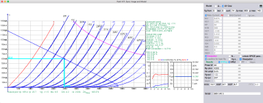
This is a graph of static settings for amp in this topic. Very close biasing point as measured.
The power is about 3.06W, THD=3,12%
input Ug=54 Vp-p
View attachment 1442158
Looks to me like this tube would be a good candidate for class A2 operation
Hooman, thanks for the encouragement 😀. I'm building it on a Tubelab board, switchable Pentade /Triode.
Recently built a GU50 (SSE), with G2 & G3 strapped to the anode and it sounded WOW (Softone RW--20 OPT). So, I thought lets give the 307a & 2e22 a shot.
I have a plan of building 2E22 SE ampli. Could anyone give me specs and plate curves of this tube in triode mode.
Thank you and regards,
Thank you and regards,
- tcqanh
- Replies: 28
- Forum: Tubes / Valves
It's very interesting to hear good sound from cheap tubes. This is an art. Regarding the maximum g 2 voltage... it is listed in the manufacturer's data as 250 volts. Does anyone know about this?
- Home
- Amplifiers
- Tubes / Valves
- Tube 2E22 in triode mode