Yes. Jut an emitter follower. As the V on the emitter is supposed to follow the one on the base, if you have a single cap there, it is a so called "cap mutiplier", but if you regulate the tension here, you have a stabilized PSU. Zeners product some noise, you can improve this part, and use Darlingtons to increase ß.of the power transistor.Mike, Esperado's with TL431 and zeners you linked is just a series regulator not a multiplier or some combo..
There is a reason why i made this choice, instead of a full regulated PSU. I noticed that those kind of PSU sound better (more relaxed) for power stages than the ones with Feedback loop inside. And they are simpler.
Why ? I suppose that two different servos in serial (The one in the PSU and the one in the FB AMP) interact between each other.
Agree ?
If someone here can evaluate and compare the two solutions, my old eyes make soldering work those little components is painfull for me now :-(
On a theoretical point of view, the PSU would need to have a > X10 bandwitch than the amp one in his feedback loop. Impossible.
It would be interesting to evaluate too the interest to charge a regulated PSU with CAPS at the output. All Happens at HF, and electrolytic caps are not so good here. After all, a PSU is an amp witch amplify a constant voltage.
Too i'm pretty sure that FETS will be better as PSU power units, as the are faster with hight currents than bipolars and all matters at HF ?
If i had time and courage to evaluate, i would try to add Powerfets on the board itself, right on the AMP power transistors sources, and try different solution to make-them regulate the voltage right there.
For the previous amp's stages, i believe any low noise solution (CSS etc... ) is perfect.
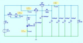
Its a nice & simple to make regulated power amp PSU the one you use. Uses feedback of course, its at the chip's ref lead. The 1mF capacitors you tie from ref adj resistors add some AC feedback too beyond filtering the combo Vref noise and its good because it augments its effectiveness by several dB. The fact that its already applied and passes your subjective tests also, makes it a standard solution for anybody who would like to evaluate his SSA or TSSA regulated.
Our spice methods are slightly different. To test line & load regulation I add a 1V AC source at input and later at output and spice gives me a graphs with -xdb.
I'm not so familiar with LT spice are you adding noise to line & load simultaneously to check regulation or is your method different ?
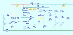
I think a Jfet with a higher idss & resistor might give a higher impedance but perhaps in this case this is not necessary.
AC1 on the pics means AC small signal analysis is activated with value of 1. The source ripple and load play values I add are showing to compare in-out when transient analysis is the mode.
That JFET gives 3-4mA average IDSS in GR selection. I put it here for two reasons. Low Vgs(off) gives more tolerance for lower Vin-Vout, has enough transconductance. Many Jfets could be applied. That config it was about Jap parts I have in hand, nothing as ''best combination''. The TO-220 driver Q2 has the grunt, and some housekeeping as Sonny reminded regarding base resistors etc. will be necessary when you will build it to test its stability and subjectivity with any adequate semis you have easier access to.
Are we really shure this will sound better that Salas's proposed cap multipier ?
I never made a regulator for a power amp o/p stage before.
I heard that nothing can substitute for the immediate power of charge pre-stored in a capacitor so I'm wondering how much capacitance people are planning to use after the regulator ?
Make them and you will judge. Just expensive heavy coils, economical very simple multiplier filter, regulated. You got all the parts.
Because I will have some chokes upstream with some series resistance and because I like the idea of having fixed rail voltages, independent of mains fluctuations, if I do an FB free regulator it will probably be something like this.
A kind of combination of ideas from Christophe & Salas.
A kind of combination of ideas from Christophe & Salas.
Attachments
Last edited:
p.s. I just added 22,000uF across the 1000uF caps on the boards - very nice.
Sound is more composed & smoother and bass is fuller & more defined.
It now sounds like a very high class amp.
Sound is more composed & smoother and bass is fuller & more defined.
It now sounds like a very high class amp.
Big electrolytic caps are not so good for "immediate power" because of their serial inductance.I heard that nothing can substitute for the immediate power of charge pre-stored in a capacitor so I'm wondering how much capacitance people are planning to use after the regulator ?
It is particularly important for our SSAs, because of their huge bandwidth.
And because the amps efficiency reduce at hf, they ask more current at HF for the same level than in middle range. Just where electrolytic caps are not able to provide it fast enough.
Paralleling big electrolytic caps with film caps will not make the trick, as they will resonate at quite high impedance at HF with the self of the big ones.
So i believe that the only very good solution would be an ultra fast low noise regulated PSU, (aperiodic) using only 3.3 or 10 µf Metallized Polypropyl film caps in their outputs and current source of the amp's power transistors to reduce the impedance at HF.
All the matter will be to ensure there is no problem on the rails during high transients.
Impossible to simulate, OMHO, only testing in real world. Comparing results in listening.
After adding these 22,000uF caps I realise that with this very low gain amp the influence of qualities of the PSU is much greater than with more "normal" amps.
So whether we like very detailed & dynamic or very soft & smooth or anything in between . . . we can control it with our PSU design.
I think I will build the supply with feedback so I can research the effects of different PSU impedances on the sound character of this & other amps.
So whether we like very detailed & dynamic or very soft & smooth or anything in between . . . we can control it with our PSU design.
I think I will build the supply with feedback so I can research the effects of different PSU impedances on the sound character of this & other amps.
I believe it is due to his quality on one side (more transparency reveal more slight differences) , and to his low PSRR on an other.After adding these 22,000uF caps I realise that with this very low gain amp the influence of qualities of the PSU is much greater than with more "normal" amps.
Good choice, as you can remove easily the feedback to compare.I think I will build the supply with feedback so I can research the effects of different PSU impedances on the sound character of this & other amps.
I'm pretty curious to read your conclusions.
If you can, please try several electrochemical caps in // versus big ones, and different values after the PSU too.
Not to forget that, if you feel your amp have less consistent basses with paralleled caps, it can be because trebles are better 🙂
So i believe that the only very good solution would be an ultra fast low noise regulated PSU, (aperiodic) using only 3.3 or 10 µf Metallized Polypropyl film caps in their outputs and current source of the amp's power transistors to reduce the impedance at HF.
Not sure about CFB amp, but in VFB amp, using only Film Cap upto 10uF does wonders to the mids and highs; sounds as liquid as a good tube amp, however, the bass is not as tight as desirable.
Hence, I would say from my experience that the following sequence in the power supply regime might help: Transformer-Rectifier-CRC Filter (optional)-Voltage Regulation-Big Capacitor Bank (on its own board or chassis mounted)-Moderately twisted Power Supply cables (as advocated by D.Self) to Amp Board-Film Caps of upto 200uF on Amp Board close to output stage.
I would say: rectifier and filters -> Big Capacitor Bank -> Ultra fast Voltage Regulation-> Big chemical caps or film ? -> Moderately twisted Power Supply huge cables (mono conductor is best) -> Board-Film Caps of up to 200uF on Amp Board close to output stage.Hence, I would say from my experience that the following sequence in the power supply regime might help: Transformer-Rectifier-CRC Filter (optional)-Voltage Regulation-Big Capacitor Bank (on its own board or chassis mounted)-Moderately twisted Power Supply cables (as advocated by D.Self) to Amp Board-Film Caps of upto 200uF on Amp Board close to output stage.
About basses, there is no reason, as long as we don't see on the supply rails any slow voltage changes to believe that big caps would be better there.
If we feel any improvement like "more tight basses" with big caps, we can suppose a lack of treble, or fast transients.
From a theoretic viewpoint in spice this is the regulator with the best performance with regards to o/p Z, speed & stability but I will use sockets etc on the prototype so I can test an all BJT version as well.
I think with this HF performance this offers I can make do with much smaller chokes upstream perhaps 10 - 50uH will surfice - or maybe I will not need any at all !
Any final comments from the experts ?
I think with this HF performance this offers I can make do with much smaller chokes upstream perhaps 10 - 50uH will surfice - or maybe I will not need any at all !
Any final comments from the experts ?
Attachments

That kind of stuff ? http://www.connexelectronic.com/documents/CW2A.jpgI think with this HF performance this offers I can make do with much smaller chokes upstream perhaps 10 - 50uH will surfice - or maybe I will not need any at all !
I am not able to participate before monday. But it Nice to see that you all take the AMP as basis and improves its performance by design a voltage regulator.
Hats off to Mike, Salas and Cristophe .. I am impressed!
Salas: have you build it?
Hats off to Mike, Salas and Cristophe .. I am impressed!
Salas: have you build it?
Salas: have you build it?
As I wrote to Mike I am several projects behind.😀
That kind of stuff ? http://www.connexelectronic.com/documents/CW2A.jpg
Ahhh - yes that kind of stuff but not quite exactly . . .
I prefer my chokes after the bridge then I can clean up the mains & diode switching noise all in one stage.
Also chokes excel in a low voltage high current environment - a small value has a bigger effect.
Last amp 18kg - perhaps next one only 9kg 😉
mike 🙂
Sonny, why R11,12,13,14 feedback network resistors are 0.5W designated in the BOM? How much RMS power your sim gives on them in full output swing? Having some 0.25W 1K good quality resistors I wanna know if I must get new double sized or not. Thanks.
P.S. I see in BOM C1,12,13 as 10nF/100V FKP2 (part decal). But they should be 47pF don't they? At least for C12,13 which are the Miller caps. Give me value confirmation, and I will get them in Silver Mica. R30,R31 0.05 Ohm 3W are scarce, will 0.1 Ohm 3W instead be a problem?
P.S. I see in BOM C1,12,13 as 10nF/100V FKP2 (part decal). But they should be 47pF don't they? At least for C12,13 which are the Miller caps. Give me value confirmation, and I will get them in Silver Mica. R30,R31 0.05 Ohm 3W are scarce, will 0.1 Ohm 3W instead be a problem?
Sonny, why R11,12,13,14 feedback network resistors are 0.5W designated in the BOM? How much RMS power your sim gives on them in full output swing? Having some 0.25W 1K good quality resistors I wanna know if I must get new double sized or not. Thanks.
P.S. I see in BOM C1,12,13 as 10nF/100V FKP2 (part decal). But they should be 47pF don't they? At least for C12,13 which are the Miller caps. Give me value confirmation, and I will get them in Silver Mica. R30,R31 0.05 Ohm 3W are scarce, will 0.1 Ohm 3W instead be a problem?
Sorry for my late response.
I have used 1/4watt resistors and with music signal it is not a problem. If you are going to run the amp with an sinewave over longer time you have to choose 1/2watt resistors. The reason is that good quality resistors can widstand higher pulse power for a short time.
The Part decal 10nF/100V FKP2 means that the layout for the wima caps are the same as for 10nF, but it is 47pF you should use.
R30 and R31 0.1R 3W together with ALF16 is just fine.
- Status
- Not open for further replies.
- Home
- More Vendors...
- SITO Audio
- TSSA V1.6 docs and buyers list