Marc..First mail brd file was 30.12.2013
Sorry but i didn't save the mail so haven't your mail anymore.
Marc
An externally hosted image should be here but it was not working when we last tested it.
like this??
An externally hosted image should be here but it was not working when we last tested it.
like this??
You don't have to cut output tracks if you follow LC schematic as there is no output device, only CCS. You just have to put on a wire betwwen output and spads
Marc
Course to GND.And the red cancel??
An externally hosted image should be here but it was not working when we last tested it.
Course to GND.And the red cancel??
An externally hosted image should be here but it was not working when we last tested it.
Yes, one more time it's only for test pocedure witout output device soldered. You don't have to cut any tracks just run a wire from output terminal to GND terminal for CCS test witout any other parts soldered as they specifed on schematic i join above
Marc
Last edited:
I want amplifier normally use, not tested!
I can nothing more for you. Up to date i never ended it....This project must going through debugging process and the first step is testing CCS as LC shown. As you discover the 2N issue, to the board must be modified to be running correct. Etch a new one modifed and solder on parts indicated by LC....an only than LC could help to go foward and validate the first step.
Marc
Transistors 2N I gave to Scheme.Try and see
Thanks Marc
PS-when you look at it ???
Yes i take a look allready and allready modify my eagle file. Give my your mail by MP or send me a mail i neither have yours.
Marc
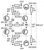
Can I use MJL4281A and MJL4302A in the TSSA amp? I have many of them doing nothing so I want to put them to good use.
Is 4 ohm operation ok for the TSSA?
Thanks
Is 4 ohm operation ok for the TSSA?
Thanks

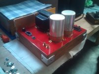
I finished my little TSSA BJT amp. There are so few parts I probably could of done it P to P but I've been trying to get better at laying out and making pcb'. It sounds pretty good. I'm using 2SC5200/2SA1943 output trans. My power supply is pretty standard, unregulated, 20,000uF per rail, 200va transformer.
Will this amp also handle a little over +-40vdc rail? I'd like to try it-out P2P and house it on this Tube like chassis that I built out of recycled materials. I could replace the BC550C/560C with the higher power BC556B/546B. Any other values that needs adjusting?
Many Thanks!
Attachments
I'm hoping someone more knowledgeable will jump in here. I'm just not sure. I think the purpose of that circuit schematic was to show how simple the TSSA can be but would probably need some support parts to beef it up with higher rails and bigger wattage. Good luck.
The basic circuit relies on high class A current. So to perform just decent it should operate at atleast 2A idle ... So rising the voltage to 40v means a lot of heat. Also the arrangement with collector into base of the output device with no basis to emitter Resistor to turn the power transistors fast off would mean slow turn of as soon as it leaves class A.
My tssa v2 to V8 is a lot more complex to keep it all running as you already had figured out. But Then it is possible to run it In class AB without sacrisfying Performance
Sent from my iPhone using Tapatalk
My tssa v2 to V8 is a lot more complex to keep it all running as you already had figured out. But Then it is possible to run it In class AB without sacrisfying Performance
Sent from my iPhone using Tapatalk
- Home
- Amplifiers
- Solid State
- TSSA - The Simplest Symmetrical Amplifier