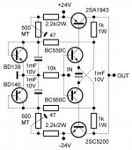
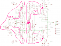
I hesitate to post this because I'm not sure if it's good or not. I've included three attachments. One of the Lazy Cat TSSA BJT circuit, second, of my pcb layout with component values and third, my pcb layout without component values. I layed out the pcb's in a program called DIYLayout Creator. I've been using it a lot for simple guitar stompboxes and small power amps. I know that I should just bite the bullet and learn Cadsoft Eagle. I was hoping someone could take a quick look and see where the glaring errors are or if I should just scrap the whole thing and use a better pcb editor. I've seen the layouts that Ales MM and a few other do here and there so good. (Beyond good). I just wanted to etch my own all bjt version of the TSSA and listen to it. You won't hurt my feelings if it stinks.
Tom
Cute little amp!!
How much power does it produce?
Can it handle 4 ohm?
I finished my little TSSA BJT amp. There are so few parts I probably could of done it P to P but I've been trying to get better at laying out and making pcb'. It sounds pretty good. I'm using 2SC5200/2SA1943 output trans. My power supply is pretty standard, unregulated, 20,000uF per rail, 200va transformer.
Attachments
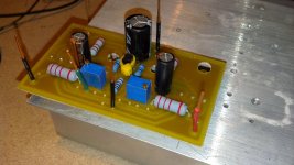
I finished my little TSSA BJT amp. There are so few parts I probably could of done it P to P but I've been trying to get better at laying out and making pcb'. It sounds pretty good. I'm using 2SC5200/2SA1943 output trans. My power supply is pretty standard, unregulated, 20,000uF per rail, 200va transformer.
Nice built Ripcord

Yes the circuit completely correspond with its acronym The Simplest Symmetrical Amplifier and this simple schematic is the base ground to all VSSA and later circuits based on this schematics. Its so stable behaviour makes it perfect to evolve to more complex and powerful designs.
Congratulations

Thanks to you Lazy Cat. The Hexfet version is in my future. To maouna, I wish I could tell you about all the technical aspects of this amp but I'm still a novice. I just really love building little power amps. The way I set it up was probably totally wrong but I just matched up the resistances on the two 500 ohm pots until it sounded good to me. It was around 350 ohms. I 'd love it if someone could tell me the procedure for checking bias and setting the pots.Thanks.
I just really love building little power amps. The way I set it up was probably totally wrong but I just matched up the resistances on the two 500 ohm pots until it sounded good to me.
😎
You're probably close with trimmers, but the purpose of these two trimmers is to set proper DC quiescent current for the output transistors and at the same time to have 0 V output DC offset.
I would definitely recommend to use the lateral mosfet outputs, less problems with thermal stability in TSSA circuit and much easier drive for the input pair. But it is good to know that even with bipolars TSSA sings. 😎
2N5486 is poorly marked,scheme is ok,G should be connected to the emitter.
An externally hosted image should be here but it was not working when we last tested it.
Has anyone built and functional??Thanks
As I remember this PCB was designed by Idefixes. I think Marc connected gate correctly, but please post sch and I can comment. 😉
I check another time and there is an effectiv mistake in my 2N5462/5486 eagle lib...i made the correction up to time.
Marc
Marc
An externally hosted image should be here but it was not working when we last tested it.
And what? i know perfectly this schematic; the issue is in the pin assignation in 2N5462/5486 eagle lib. I correct it and and the layout therefore.
Marc
Anyway amplifier is not working properly ...problem with bias current.Give a scheme with a voltage.. moment.
Thank you for the correction image.
Thank you for the correction image.
An externally hosted image should be here but it was not working when we last tested it.
bias 10mA,at these voltages.
Last edited:
Anyway amplifier is not working properly ...problem with bias current.Give a scheme with a voltage.. moment.
Thank you for the correction image.
Have you search in the topic : LC given a TSSA Schematic with the first parts to built in with the backround to test CCS. These can not IMO been functionnal with 2N5486/5462 mistake.
I join you LC schematic. I solder all these parts on my board but never does the test...this should shown me that 2N Jfet are wrong on my layout...
Marc
Attachments
Anyway amplifier is not working properly ...problem with bias current.Give a scheme with a voltage.. moment.
Thank you for the correction image.
Give another time your mail that i send you modified layout...but as i never built it and test complitly be award and check another time my work
Marc
Yes you must connect this point to GND through a wire for testing procedure. You do this by shorting "speaker Out" spad to "GND spad"
Marc
Marc
Last edited:
- Home
- Amplifiers
- Solid State
- TSSA - The Simplest Symmetrical Amplifier