Whenever i hear my records on much better set up i get the same impression.Music seems slower!Not like transients are slow but the tempo of the music seems different.
i did some changes that affected the hum level.
In the first test there was no hum.
But because we raised the current through the input pair and changed it to a CFP pair we need PMBFJ174 (PMBFJ111) instead of PMBFJ175 (PMBFJ112) which i did not have in stock. So i removed the cascode for the input pair.
This added hum as the output impedance of the input pair was lower.
But besides from that it works very very well. Better than i believed myself.
- Sonny
i did some changes that affected the hum level.
In the first test there was no hum.
But because we raised the current through the input pair and changed it to a CFP pair we need PMBFJ174 (PMBFJ111) instead of PMBFJ175 (PMBFJ112) which i did not have in stock. So i removed the cascode for the input pair.
This added hum as the output impedance of the input pair was lower.
But besides from that it works very very well. Better than i believed myself.
- Sonny
Yes, it is much better when cascoded with j-fets, I did a lot of practical tests on CCS-s and input plus VAS gain stages. Every time tracking cascodes were in use the results were better regarding bandwidth as well at noise level, more stable also.
I am impressed how only two stages amp of yours is well performed because it is only powered VAS if we look to normal VAS schematic.
I decided as always, that my amps also have normal output stage after VAS and at least two pairs of power devices at +/-60 V, to use benefit of std 63 V ELCO-s.
Now I am at final QC of CSA PCB-s which will go into production next week.
Regards Andrej 😉
Sonny I think your result is marvelous... Truly outstanding mids and highs. In this respect it's clearly better than my current mirrored version of the SSA, that in return is a true killer in the base. I think I'll take the mirrors away to see how a simpler resistor loaded VAS performes.. hope to find your resolution and sparkle in the mids and highs...
Always on the the track to something better... 🙂
Always on the the track to something better... 🙂
Yes, it is much better when cascoded with j-fets, I did a lot of practical tests on CCS-s and input plus VAS gain stages. Every time tracking cascodes were in use the results were better regarding bandwidth as well at noise level, more stable also.
I am impressed how only two stages amp of yours is well performed because it is only powered VAS if we look to normal VAS schematic.
I decided as always, that my amps also have normal output stage after VAS and at least two pairs of power devices at +/-60 V, to use benefit of std 63 V ELCO-s.
Now I am at final QC of CSA PCB-s which will go into production next week.
Regards Andrej 😉
I am also surprised How well it works.
The cascodes does a good job. You could send a screenshot if you want me to look at your pcb design.
I think 63V elco for 60V supply is a bit underrated. I would prefer at least 80V.
Last edited:
Michael i Think you should be proud of your latest layout. It looks good and it does Sound good as well.
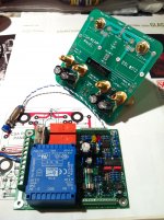
Andrej i Think we need to meet some day. Your assembly skills looks good. Very good.
Andrej i Think we need to meet some day. Your assembly skills looks good. Very good.
Thanks Sonny, experiences from the past should make some difference hehe
SSA is small 30 x 30 x 12 cm, 20 kg, but it rocks very hard, Piegas can be loud as hell.
Yes it would be nice to meet you guys some day, probably me driving across Europe later this year, of course with CSA in the car. 😀
Micheal could you show us some photo of your SSA amp, I'm really curious ...
SSA is small 30 x 30 x 12 cm, 20 kg, but it rocks very hard, Piegas can be loud as hell.
Yes it would be nice to meet you guys some day, probably me driving across Europe later this year, of course with CSA in the car. 😀
Micheal could you show us some photo of your SSA amp, I'm really curious ...
SSA is small 30 x 30 x 12 cm
Sometimes I wonder, how much of that compact assembly contribute to the success of your amp sound-wise. I always like short connections but I have had difficulty to design a "PCB" where the RCA connection is on the PCB (so no cable). I will do it for sure when I have found my final amp 😀
BUT, small amps (boxes) don't look good to me. I prefer the standard width so it will look good if had to be stacked on top of other standard sized components.
Sonnya, i am interested how the schematic looks of the amp you brought to Michael.
Have you tried the J-Fet cascodes in the meantime ?
If you wish i can send you J112 and J175, selection is possible.
Have you tried the J-Fet cascodes in the meantime ?
If you wish i can send you J112 and J175, selection is possible.
Updated schematic TSSA release V1.0b
Hi all. After some vacation in Bibione Italy i am back to work.
I have attached the schematic for the the amp in the present state. It runs very very will.
There is a little hum close to the speaker, but that will be fixed.
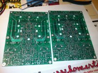
The board layout will be changed this week. And hopefully next week the board will be released. 😉
Hi all. After some vacation in Bibione Italy i am back to work.
I have attached the schematic for the the amp in the present state. It runs very very will.
There is a little hum close to the speaker, but that will be fixed.
The board layout will be changed this week. And hopefully next week the board will be released. 😉
Attachments
Hi all. After some vacation in Bibione Italy i am back to work.
I have attached the schematic for the the amp in the present state. It runs very very will.
There is a little hum close to the speaker, but that will be fixed.
The board layout will be changed this week. And hopefully next week the board will be released. 😉
Welcome back Sonny 😉
I am also fully occupied with CSA build. CSA is maybe even better performer, yes IMHO hehe
Hardly wait to see new PCB's.
All the best to you and Gerhard too 🙂
Hi mikelm
There's no CSA thread yet, only CSA amp itself in assembly phase. Will start the thread when complete the build to the last detail. CSA amp is not far away from SSA/TSSA topology except it incorporates 22 transistors and 7 TL431 in front-end stage only. So it is obvious that a lot more attention was put into the last detail, thermal stability. Also all separate parts of the front-end sch were tested separately, pushed to the limits, measured, compensated, etc. If CSA will work on present PCB it will work perfectly, until than please stand by.
Best regards, Andrej
Attachments
Sonnya, the following parts are not labelled in your latest schematic: Q11, Q18-Q21, U3 & U4. Also missing are values of R33 (ought to be 220R), all trimpots (only catalogue numbers are indicated) & Vf of Red LEDs (type LTST-C170CKT). The foregoing and details of thermal coupling (may not be necessary as Lateral MOSFETs are used) etc., will help those who want to whip their own boards. Thanks.
Open the schematic in acrobat reader, then you can click on the parts and get data.
I will update the schematic, but a little digging yourself will learn you something about the parts.
Search for the parts on Farnell / Electronic Component Distributors / Suppliers / Electronics, Electrical Parts, Electrical Components and Wholesale Electronics.
There is no big need for thermal coupling, on this amp.
But i will make docs that will follow with the boards i ship. But i will do this in the commercial section.
http://www.diyaudio.com/forums/sito-audio/213549-tssa-v1-5-a.html
Hi mikelm
There's no CSA thread yet, only CSA amp itself in assembly phase. Will start the thread when complete the build to the last detail. CSA amp is not far away from SSA/TSSA topology except it incorporates 22 transistors and 7 TL431 in front-end stage only. So it is obvious that a lot more attention was put into the last detail, thermal stability. Also all separate parts of the front-end sch were tested separately, pushed to the limits, measured, compensated, etc. If CSA will work on present PCB it will work perfectly, until than please stand by.
Best regards, Andrej
Great news, LC! Boards look....simple 😀
- Home
- Amplifiers
- Solid State
- TSSA - The Simplest Symmetrical Amplifier