Frank, do you know where i can get some of these (at a decent price) ?
Your doing well chapark 🙂 I think my speaker project took about 7 years from when I first started seriously thinking about it to when it was semi finished (no it still isn't finished!!)
Before I read Moondogs post I immediately thought of coventry fasteners for the speaker screws. That's where I got my button head allen screws. They look nice and shouldn't cause any nasty diffraction effects.
I just dug up the receipt. part # 4X30MBHSS 24 off $14.73 incl GST
24 X Hex nuts to suit $1.03 (note that trying to glue in hex nuts on the reverse of the baffle is harder than you might think, I think I probably should have used plastibond rather than araldite....
That was in Nov 2005. I think that they were 30MM long (front baffle 25MM)
So not exactly cheap but not going to break the bank either... I needed 16 and got some spares.
Tony.
Looking very good so far.
What software are you using for DSP? Do you have many options for EQ?
Eventually, to take advantage of the DSP possibilities, you will need some means of measuring response. Look into the RTA programs and get a cheap probe mic.
David S.
What software are you using for DSP? Do you have many options for EQ?
Eventually, to take advantage of the DSP possibilities, you will need some means of measuring response. Look into the RTA programs and get a cheap probe mic.
David S.
Thanks all for your friendly comments!
For now i'll stick to these ugly screws that i have. They were cheap and they do their job. In the future, if it happens that the sound coming out of these speakers is acceptable, i'll probably paint them and change the screws for better looking ones. Coventry Fasteners have an online catalog and it seems they're quite expensive for imperial screws...
@ Wintermute: i had a look at your speakers, they look really good! Hey instead of trying to glue hex nuts to the back of your panel, check out the hurricane nuts at PE, i confirm they work really well.
@ Speaker dave: i'm using a processor which is not intended for this application but offers basic filtering see orfeusz206 at WAF - Wroclaw Audio Force. I already own a measurement microphone, i'll post a few graphs some day 🙂
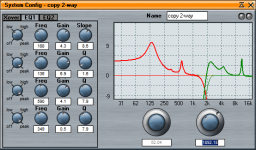
So i've used part of this rainy saturday to quickly hook up a measurement microphone and look at the frequency response as a start.
So far the xover and eq has been set by ear and it's still a FIR (169 coefficients with splitting frequency around 1800 Hz), slightly below Eton's recommendations for their tweeter (2000 or 2500Hz depending on the version of the product specs). There's also a slight shelving filter IIR with 3dB gain for the bass with fc at 180 Hz, and the tweeter is attenuated by 2dB.
So here are the plots:


Microphone was not compensated for but is relatively flat according to the calibration file from the manufacturer (+/- 1dB). Measurements were taken in the living room and include room effect as well as everyday's life noise...
So far the xover and eq has been set by ear and it's still a FIR (169 coefficients with splitting frequency around 1800 Hz), slightly below Eton's recommendations for their tweeter (2000 or 2500Hz depending on the version of the product specs). There's also a slight shelving filter IIR with 3dB gain for the bass with fc at 180 Hz, and the tweeter is attenuated by 2dB.
So here are the plots:
Microphone was not compensated for but is relatively flat according to the calibration file from the manufacturer (+/- 1dB). Measurements were taken in the living room and include room effect as well as everyday's life noise...
@ Wintermute: i had a look at your speakers, they look really good! Hey instead of trying to glue hex nuts to the back of your panel, check out the hurricane nuts at PE, i confirm they work really well.
Thanks! 🙂 I think I'll have to get some of those hurricane nuts for my next project! what size thread are they? M5?? They look much better than T-Nuts that I had contemplated.
Those measurements look very good to me if they include room effect! My in room measurements have been shocking! I think my main issue is that the listening position is against the wall.
Tony.
I think I'll have to get some of those hurricane nuts for my next project! what size thread are they? M5?? They look much better than T-Nuts that I had contemplated.
Tony, forget about metric threads if you get into hurricane nuts 🙁
For the ones i had ordered, i needed to get 5/12" screws which is a real pain in Sydney.
Ok I'm back with some stuff.
So here's the right loudspeaker response:

After following tweaking (i've slightly moved the split freq):

The response at same location is looking like that:

Same punishment for left channel:

And the result:

Looks quite OK, but one would need to have a listening session with it.
That's what i'm currently doing, with Freedie Hubbard 'Hub-Tones'
So here's the right loudspeaker response:
After following tweaking (i've slightly moved the split freq):
The response at same location is looking like that:
Same punishment for left channel:
And the result:
Looks quite OK, but one would need to have a listening session with it.
That's what i'm currently doing, with Freedie Hubbard 'Hub-Tones'
Attachments
Hi all, more work done this week, here are some pics.
![100_1755[1].jpg](https://www.diyaudio.com/community/data/attachments/211/211197-72d1dcbb1fdf77f0673295120cf9e036.jpg?hash=ctHcux_fd_ "100_1755[1].jpg")
![100_1753[1].jpg](https://www.diyaudio.com/community/data/attachments/211/211198-f1d51d6ad29764104eabe4f11bab3ab3.jpg?hash=8dUdatKXZB "100_1753[1].jpg")
![100_1758[1].jpg](https://www.diyaudio.com/community/data/attachments/211/211202-92351046bd50573dba8c10d53dabe8f2.jpg?hash=kjUQRr1QVz "100_1758[1].jpg")
Next stage is going to be bottom end measurement and tweaking.
Cheers
chaparK
Next stage is going to be bottom end measurement and tweaking.
Cheers
chaparK
Thanks Bart!
Well, regarding the bass response i'm going to start with a LT transformation. According to the manufacturer, the woofer has plenty of excursion - 12 mm peak to peak linear travel and 26 mm max before destruction so it might be a good candidate for such a tweak.
Here's the frequency response of the manufacturer:

I made today quick nearfield measurements and here's what i'm getting:


Both channels are pretty similar but i don't really understand the dips at 400 Hz and 1800 Hz? 😕 Any idea? Other than that F3 is around 72/74 Hz.
The internal volume of the enclosure is about 17 litres, which somehow confirms that manufacturer's TS data are not accurate and that the 2 sets of TS parameters mentioned in the beginning of the thread are closer to the real thing.
17 litres yields a Qtc of about 0.9 as confirmed by a quick simulation in WinISD:

Based on this data, I quickly made a model of a LT allowing to recover one octave, followed by a 2nd order high-pass butterworth cornering at 15 Hz. That filter would transpose F3 downto 36/37 Hz.

This is the kind of tweak i'm planning 🙂
Well, regarding the bass response i'm going to start with a LT transformation. According to the manufacturer, the woofer has plenty of excursion - 12 mm peak to peak linear travel and 26 mm max before destruction so it might be a good candidate for such a tweak.
Here's the frequency response of the manufacturer:
I made today quick nearfield measurements and here's what i'm getting:
Both channels are pretty similar but i don't really understand the dips at 400 Hz and 1800 Hz? 😕 Any idea? Other than that F3 is around 72/74 Hz.
The internal volume of the enclosure is about 17 litres, which somehow confirms that manufacturer's TS data are not accurate and that the 2 sets of TS parameters mentioned in the beginning of the thread are closer to the real thing.
17 litres yields a Qtc of about 0.9 as confirmed by a quick simulation in WinISD:
Based on this data, I quickly made a model of a LT allowing to recover one octave, followed by a 2nd order high-pass butterworth cornering at 15 Hz. That filter would transpose F3 downto 36/37 Hz.
This is the kind of tweak i'm planning 🙂
I'm looking at the LT simulation and something's looking strange, don't know why. Well there is a bug.
So here's the LT i have in mind so far (with added LT + High Pass combination):

I'm now tackling the excursion problem. I understood that excursion vs frequency is the mirror of the frequency response for a closed box. This is all relative however: i'm missing the link between the normalized excursion curve (i.e. with excursion = 1 or 0dB at fc) and the real excursion in mm according to dissipated power? 😕 Any help appreciated!!! 🙂
So here's the LT i have in mind so far (with added LT + High Pass combination):
I'm now tackling the excursion problem. I understood that excursion vs frequency is the mirror of the frequency response for a closed box. This is all relative however: i'm missing the link between the normalized excursion curve (i.e. with excursion = 1 or 0dB at fc) and the real excursion in mm according to dissipated power? 😕 Any help appreciated!!! 🙂
Hi,
the LT applies ~ 12dB of boost. Adding the filter results in a boost peak ~11dB @ 25Hz.
This will almost double the excursion of any 25Hz signal.
Your 6mm Xmax is effectively equivalent to 3mm Xmax.
Your driver cannot play loud.
Asking a driver & LT to extend by an octave is too much for most systems.
Is the 130Hz to 180Hz bump just 1dB, for Qbox=0.9?
Last edited:
What Andrew said was also my first thought, so this is useful only if you're planning on low listening levels.
The higher dip might be the crossover frequency that's at the wrong frequency... The lower dip, I don't know...
But if this was very-near field, then the height of the microphone would have a huge impact.
The higher dip might be the crossover frequency that's at the wrong frequency... The lower dip, I don't know...
But if this was very-near field, then the height of the microphone would have a huge impact.
Both channels are pretty similar but i don't really understand the dips at 400 Hz and 1800 Hz? 😕 Any idea?
This is due to the nature of n/f testing and is normal.
The usable range is limited by the diameter of the driver.
Hi,
the LT applies ~ 12dB of boost. Adding the filter results in a boost peak ~11dB @ 25Hz.
This will almost double the excursion of any 25Hz signal.
Your 6mm Xmax is effectively equivalent to 3mm Xmax.
Your driver cannot play loud.
Asking a driver & LT to extend by an octave is too much for most systems.
Ignore this textbook nonsense and go for that 1 octave lower LTX.
Hi,
the LT applies ~ 12dB of boost. Adding the filter results in a boost peak ~11dB @ 25Hz.
This will almost double the excursion of any 25Hz signal.
Your 6mm Xmax is effectively equivalent to 3mm Xmax.
Your driver cannot play loud.
Asking a driver & LT to extend by an octave is too much for most systems.
Is the 130Hz to 180Hz bump just 1dB, for Qbox=0.9?
Actually i think that a 12 dB boost will even quadruple the excursion required by the signals, but it's maybe still OK. I'll post a few more simulations soon to elaborate on that.
Otherwise yes for Qbox = 0.9 the overshoot in the frequency response is less than 1dB.
Plots show the measurement of the woofer alone in the box, i.e. tweeter and crossover both disconnected.The higher dip might be the crossover frequency that's at the wrong frequency... The lower dip, I don't know...
But if this was very-near field, then the height of the microphone would have a huge impact.
I placed the microphone at woofer axis elevation, capsule about 1 cm away from the dust cap.
This is due to the nature of n/f testing and is normal.
The usable range is limited by the diameter of the driver.
 Is there a rule of thumb for having a rough idea of how far the nearfield measurement is a good image of the farfield one?
 You bet i will 😀go for that 1 octave lower LTX.
Thanks all for your inputs and comments, very much appreciated! 🙂
Here's an other simulation with some insight on excursion requirements. It shows the effect of 2 high-pass filters: one as above (2nd order BW cornering at 15 Hz) and the other 4th order BW cornering at 25 Hz.

Right-hand plot shows relative excursion where unity is the excursion at low frequency for the unequalized loudspeaker.
What i need now is to take into account the signal power in order to derive similar curves with absolute excursion (in mm). Don't know how to do that, but i'll find.
Right-hand plot shows relative excursion where unity is the excursion at low frequency for the unequalized loudspeaker.
What i need now is to take into account the signal power in order to derive similar curves with absolute excursion (in mm). Don't know how to do that, but i'll find.
According to my findings, the LT transform will not destroy the woofers even if the amp is pushed to the max. But well in any findings there's space for mistakes.
Anyway i've made a test of a LT lowering f3 from about 72 downto 40 Hz and simulating a maximally flat box loading. There's a 2nd order Butterworth HP cornering at 25 Hz to help protecting the driver.

It actually sounds rather nice. I'll probably experiment with some other combinations of Qt/f3.
Anyway i've made a test of a LT lowering f3 from about 72 downto 40 Hz and simulating a maximally flat box loading. There's a 2nd order Butterworth HP cornering at 25 Hz to help protecting the driver.
It actually sounds rather nice. I'll probably experiment with some other combinations of Qt/f3.
That looks promising!
Keep us posted on a listening session please.
Would you mind sharing some circuit-details?
Keep us posted on a listening session please.
Would you mind sharing some circuit-details?
That looks promising!
Keep us posted on a listening session please.
Would you mind sharing some circuit-details?
Thanks Bart. I'll tune the LT and shape the remaining of the response and then i'll do some serious tests with measurements.
Regarding the circuit it's all implemented in DSP.
In order to implement such a LT, one need:
1. To measure the impedance of the woofer in the box. The bell shape lets you extract the Q and Fc of the system. This is what you want to undo.
2. You specify the new target, i.e what Q and fc you'd like for the final system. With this and 1. above you get all the data for a 2nd order filter in the continuous time-domain (s plane).
3. Optionally you can specify a high-pass filter. In my case i selected a second-order butterworth.
4. The final step is about transforming your s-plane coefs into z-plane ones. I used a bilinear transform which seems well suited because it's all happening in the low frequencies.
5. Implementation is straightforward, it's only a pair of biquads per channel.
chaparK
- Status
- Not open for further replies.
- Home
- Loudspeakers
- Multi-Way
- TS parameters & closed-box design