The complexity is what makes it fun! 🥳Fun, so we are in the mystical area of the science now.
Depending on how into-the-weeds one wishes to go, the entire measurement is recorded, and then inverse FFT'd into an impulse. That is where the window is applied. Then the selected amount of impulse is FFT'd back into the FR. So the amount of time the audio interface takes data is not exactly related to the window length.The gate is a window in time that is open for a certain duration - when the duration is over the gate is closed. It means that when the software that consumes the signal from the mic has the choice to listen a certain time before and after the actual measurement stimuli.
If you use REW and set the window to 1 ms you will see that the presentation stops at 1k. So no other "resolution" degradation than the lower cut off frequency - all data above is full "resolution" and contains no smoothing as in "Smoothing" in REW. So why does it (most often) look smoother - well you get rid of the reflections
Well, no smoothing as a post-processing step has been applied. The FFT back to FR has a lowest frequency bin, as you noted. The bins are linearly spaced, and we like to look at frequency on a log scale. If the lowest bin is at 1k, the next bin is at 2k, the next at 3k, etc etc. So at high frequency you get good resolution, but if you want to see what's up at 1.5k not so much. The resolution would appear uniform if you were looking at a linear frequency scale, but nobody does that.
https://www.ap.com/news/more-about-ffts
Last edited:

I'll be honest. I still only partially understand this. So there is a resolution factor happening here where the further I gate out the higher the resolution of the frequency response above my gate? But as it gets that resolution it is also including reflections?
Open IR windows when you are changing the window width. It displays the Freq. resolution (which is the correct term), for the chosen widow width / gating.
Say you have a 10ms window /gate. That is a freq resolution of 100Hz (1000ms/10ms)
Compare that 100Hz resolution to octave bandwidths.
For the top octave 10kHz -20kHz, which spans 10,000Hz, 100Hz resolution can be thought of as 1/100th smoothing. (100/10,000). High resolution for sure.
Take the octave 125-250Hz, which spans 125Hz. 100Hz resolution not so good, huh? 🙂
Thing is a linear freq resolution on log width octaves, create a different implied 1/Xth smoothing for each octave.
So really, there's no such thing as a 'lowest frequency vs gating" ....as it's a judgement call on low a resolution you consider usable, given the situation.
Yeppers. That's perhaps the very first lesson, in FFT audio measurement.https://blog.teledynelecroy.com/2013/09/back-to-basics-what-is-fft.html
"The capture time, T, determines the frequency resolution of the FFT (Δf = 1/T)."
I believe that what you are seeing is the result of diffraction, and reflections off of the rest of the speaker. The longer the gate, the more accurate the response, but only up to the point where the reflection is from something other than the speaker.
A gate of 4ms is fine for a tweeter to mid-range for x-over work. With your 8' setup, you can gate a lot lower, but there is not much need to do so. The woofer to mid can require a bit longer gate, unless you work outside the box, so to speak, and measure in creative ways.
A gate of 4ms is fine for a tweeter to mid-range for x-over work. With your 8' setup, you can gate a lot lower, but there is not much need to do so. The woofer to mid can require a bit longer gate, unless you work outside the box, so to speak, and measure in creative ways.
Possible, I never thought about that.I don't remember what you used when measuring the HiVi, but for the latest it could be reflections from the mic holder you printed.
http://www.troelsgravesen.dk/measurements.htm
Very similar results. I think these ripples are reflections off of surfaces around the tweeter.Here's a few examples from my center channel. Different gate, and smoothing.
I suppose this is why you sometimes see a tweeter in its own little ball enclosure on top of the rest of the unit.
your impulse image has no detail, zoom in
look at the attached image, red is the stimulus at 1mS
at around 2.8mS we have the output of the dut in yellow
and at around 5.7mS is the first reflection
to gate out this reflection, the marker is set just before it, say 5.5ms

look at the attached image, red is the stimulus at 1mS
at around 2.8mS we have the output of the dut in yellow
and at around 5.7mS is the first reflection
to gate out this reflection, the marker is set just before it, say 5.5ms
Whilst ever the surface follows the travel of the wavefront, there is only support for it and not distinct reflection.I think these ripples are reflections off of surfaces around the tweeter.
If a driver is appropriate for a baffle then removing the baffle creates maximum diffraction with close timing. Some can get away with it for psychoacoustic reasons.. but then you still have minimum directivity control.I suppose this is why you sometimes see a tweeter in its own little ball enclosure on top of the rest of the unit.
I honestly forgot about this. Aspect. Here is the tweeter zoomed in. Yes, it is a very good impulse response.your impulse image has no detail, zoom in
look at the attached image, red is the stimulus at 1mS
at around 2.8mS we have the output of the dut in yellow
and at around 5.7mS is the first reflection
to gate out this reflection, the marker is set just before it, say 5.5ms
View attachment 1420386
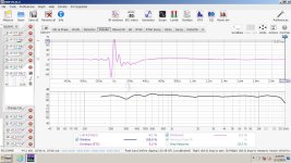
Not sure what that little purple squiggle is right after the impulse but the ripples come immediately after that squiggle.
No squiggle.
Annnnddddd.....squiggle
So lets run some logic and deduction. That squiggle is at 2500hz almost exactly. A 2500hz wavelength is 132mm long. So this ripple must come from a reflection that is within 132mm of the source right?
If I draw a square offset from the tweeter edge 132mm and a circle offset 132mm from the very center we get this:
Our possible culprits then are then
1. The bolt heads which can easily be swapped or modified for some other fastener
2. The beginning of the curves around the other drivers
3. The ginormous rubber surround of the woofer.
4. The edge where the face meets the body. This enclosure is two pieces.
The mid seems to have a similar thing going on just closer. At 0.1 microseconds which would in infer just a hands count of milimeters.
This could very well be this very small gap between the face of the planar and the back side of the face piece of the enclosure.
If all of this is true and not inherent to the drivers themselves then what would be suggested to fix them?
The mid I can test very easily. I have a laser machine at work and I can laser out a 1/8" closed cell foam gasket. Place it inbetween to ensure there is no gap. I can also just modify the face so that it touches directly onto the face of the planar. This requires a reprint but that is easy enough.
If the reflection on the tweeter is actually the surround, the only fix I can think of is trying to move the tweeter forwards. Alternatively, I could move the woofer back in towards the body of the enclosure so that the surround no longer sticks out. I would have to redesign a bit of the enclosure to make this work but its just some tappy tappy of my mouse for an hour, then a reprint.
Moving the woofer back in the XO sim actually shows improvement. Advancing or retarding the tweeter causes problems. I spent a decent amount of time ensuring the moving parts of the planar and ribbon were physically aligned. Moving them will cause problems. I think I ended up within 1mm of dead on which I consider to be a bulls eye (pats myself on the back).
Thoughts? Suggestions?
If it is the surround...
Put some thick felt or denim insulation at the edge of the surround and re-measure and see if it goes away.
I get, that from a scientific point of view you would like to know what is causing it, but I don't think you should necessarily "do anything" about it. Re-plot your measurements using Psychoacoustic smoothing and see if any of this is likely to matter audibly.
Currently printing this block off plate. I'll just remove the woofer and install this.Put some thick felt or denim insulation at the edge of the surround and re-measure and see if it goes away.
I'll laser cut the gasket and test the mid as well.
If none of it goes away, I'll assume its just the drivers themselves.
This is the Parts Express FRD/ZMA file. Theirs looks even worse than mine. Maybe it is inherent in the design.

If you had one pod alone would it measure ripple free, I wonder? I like the idea also to check for reflections around your mic (that might also explain the PE FRD). Denim insulation is good for absorbing reflections, I had one setup where I had to fix a bunch of the stuff to my stand to get a clear measurement.
Several options to consider. Swap out the tweeter for one in a wave-guide. Tweeters in wave-guides don't have as many issues with diffraction.
Mount the tweeter on a 2' x 2' panel, and measure it.
Mount all three drivers on a panel, and measure.
Use one mic location at 1m, not three.
My mic is strapped to a golf club shaft, but I have held the mic by hand with my arm straight out.
Probably not happening here, but one-time, the speaker in my laptop was singing along during sweeps.
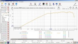
I don't totally know how to interpret these impulse measurements. I'm still learning the finer points of REW.
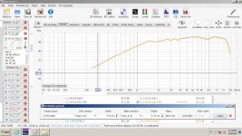
This is a small Peerless wave-guide tweeter mounted on a 11" x 20" baffle with no round over. There is a 10" RS270P almost touching it. The woofer is not recessed. The tweeter is protruding slightly, as the recess was not deep enough. I'm currently using this speaker as a center channel. It's a work in progress. What, if anything can I learn from this. I want to compare with other drivers, but I'd like to know what I'm looking at, beyond setting the gate, which I already understand.
Tweeter and then the whole speaker. (Looks like the polarity is swapped.)
Attachments

Last edited:
I hadn't noticed before, but it looks like you have created a wave-guide around the mid. That could possibly change the response.
Thoughts? Suggestions?
printing this block off plate.
Everyone seems to have more patience than I do when it comes to chasing this stuff. Leaving all drivers in their current mounts, I'd be making a pretty big flat baffle out of cardboard/Fome-Cor (whatever was within about 5 feet of me and cuts with a knife or scissors) and putting a cutout in it the size of the one driver I wanted to focus on for each measurement. Masking tape and speed are your friends. If you don't invest much time or money into the tests, it's also easier to hack things to various other configurations without concern. About 20 minutes of this while measuring will likely answer the questions.Mount the tweeter on a 2' x 2' panel, and measure it.
Last edited:
This definitely changes the response. Originally I set out to horn load this mid. I successfully horn loaded it and was getting good response and minimal disotortion down to around 380 hz, however, the horns that were effective were too large to be practical.I hadn't noticed before, but it looks like you have created a wave-guide around the mid. That could possibly change the response.
This waveguide was the best performing for its size
This is textbook what you want to see. Driver goes out, then back, then stops dead. Perfect.I don't totally know how to interpret these impulse measurements. I'm still learning the finer points of REW.
This is a small Peerless wave-guide tweeter mounted on a 11" x 20" baffle with no round over. There is a 10" RS270P almost touching it. The woofer is not recessed. The tweeter is protruding slightly, as the recess was not deep enough. I'm currently using this speaker as a center channel. It's a work in progress. What, if anything can I learn from this. I want to compare with other drivers, but I'd like to know what I'm looking at, beyond setting the gate, which I already understand.
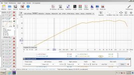
Here is what you do not want to see. This lingering ringing. Granted, this is a woofer, not a tweeter. Were this a tweeter this wouldn't be fantastic but it would still be ok
Don't take this too seriously though. This is only one parameter of a driver. This is the Zaph 5.5 that I am using a mid. It sounds absolutely fantastic. Just because the impulse isn't perfect doesn't mean its not a good driver. If you see it ringing horrendously, then yeah, its probably not a good speaker. What is above is acceptable, just not perfection.
Woofers ring more than tweeters. More moving mass to have to stop
- Home
- Loudspeakers
- Multi-Way
- Trying to understand gating in tweeter measurements