Progress!
So is the loss through the bridged-T (TP A re TP B) closer to -14dB?
Your sine wave doesn't look awful--- you sure about FFT validity?
Maybe you can remeasure AC amplitudes at A,B, cathode, bottom of lamp.
I'm about to crash for the evening. Good progress, hang in there!
So is the loss through the bridged-T (TP A re TP B) closer to -14dB?
Your sine wave doesn't look awful--- you sure about FFT validity?
Maybe you can remeasure AC amplitudes at A,B, cathode, bottom of lamp.
I'm about to crash for the evening. Good progress, hang in there!
Last edited:
The most recent DC voltage measurements indicate 6AU6 anode current = (409-165)/47k + (409-152)/120k = 5.2+2.1=7.3mA. 7.3mA through 330+12 gives 2.5Vdc, which is equal to measurement value.
But the measured values with the 6CL6 removed don't make sense at all to me.
Were those measurements taken with the bulb removed? The bulb introduces a more complex network, as would C8 if it was leaky. My thought was to try and simplify the idle circuit operation to confirm valves were operating as expected.
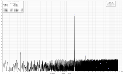
I rechecked my connection to the soundcard/PC processing FFTs. After some fiddling, I removed the plug and clamped my leads directly onto the wires. The FFT results improved... considerably. See attached.
I am prepared to accept egg on my face for however much of this problem has been caused by my poor FFT connection. Still, we caught at least one bad wire, and possibly incorrect wiring across one or both tubes.
My latest figures:
Point A: 0.204VAC, 0.57VDC
Point B: 4.3VAC, 0.59VDC
Bottom of lamp: 0.11VAC, 0.879VDC
6AU7 Pin 7: 0.204VAC, 0.57VDC
Output control: 138 ohm
Attachments
Congrats!
I don't think FFT caused any problem aside from some initial disappointment when you rechecked after wiring fix.
Your persistence has been rewarded. 🙂
I don't think FFT caused any problem aside from some initial disappointment when you rechecked after wiring fix.
Your persistence has been rewarded. 🙂
The wiring you illustrated with the PDF is not particularly "tidy" (to be kind). Blame Heathkit and the original kit builder.I rechecked my connection to the soundcard/PC processing FFTs. After some fiddling, I removed the plug and clamped my leads directly onto the wires. The FFT results improved... considerably. See attached.
I don't know where you go with the noise floor. Is it as bad as it looks? Run the FFT with more averages.
Post #43 spectrum plot may benefit from using many averages and a longer FFT length - as that should lower the noise floor to allow the harmonics to be better observed.
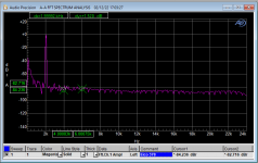
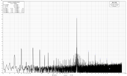
I played around with the input device settings on my laptop. Even with the input always coming from my Focusrite Scarlett, simply choosing different input device selections dropped the noise floor by 40dB. See attached. One is at the same scale as my last graph, the other has been extended to -40 to show the new noise floor.
Thank you kindly to everyone who has helped out in this thread! I am a smarter man for your efforts 🙂
Thank you kindly to everyone who has helped out in this thread! I am a smarter man for your efforts 🙂
Attachments
What you have to do is build a little T-notch filter to eliminate the fundamental into your VNA. Then you can tweek the oscillator pot to optimize the THD%
If it is entirely the same as the EICO, the oscillator output and THD% are a function of this potentiometer setting. If you don't need "balls to the walls" 10V output, can settle for 3V you can get the THD+N% down near 0.01% The trade-off, however, you have to make the oscillator work through the frequency range settings.
For the record, the meter setting pot loads the output a bit and WILL influence THD%
I think I’m close to 1v output right now, but I need to recheck. I’ll experiment with the meter control.
How does notching out the fundamental help with minimizing THD? I think I can figure out how to make the T-notch. I can just pick an arbitrary frequency to use for calibration, right?
How does notching out the fundamental help with minimizing THD? I think I can figure out how to make the T-notch. I can just pick an arbitrary frequency to use for calibration, right?
A notch filter reduces the high level of fundamental frequency that has to go through the input and ADC circuitry of your soundcard - which causes a 'phantom' level of harmonic distortion being displayed by the software, and which can mask the actual level of harmonics actually being generated by the oscillator.
Ok, I've reached a stopping point for this project for the time being. I may go back with a T-notch filter to dial in the pot even more, but for now I have it running within spec, which was my goal.
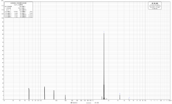
I fitted the original 1K oscillator pot, but crossed it with some 1K resistors to bring the effective range down to about 250 ohms, which is representative of the actual useful range. I tried a couple different replacement lightbulbs, two from Home Depot and one NOS bulb, although it wasn't an exact match. The original bulb bested them all by 0.5% THD. I install installed a 1.5uF capacitor before the output lug to remove a ~0.6V DC bias.
I calibrated the oscillator to a level that produces 3.2V at maximum standard output, and produces a THD range between 0.04% and 0.12%.
I could keep playing this thing forever, I think, but I need to put it to bed and move on to other projects. Thank you all SO MUCH for your help! I really appreciate you holding my hand as I struggled my way through this. I've learned a lot on this project.
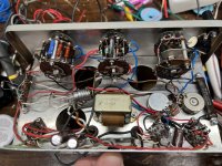
See attached for my final "professional quality" wiring job. I do think it's cleaner than it was when I got it at least.
I fitted the original 1K oscillator pot, but crossed it with some 1K resistors to bring the effective range down to about 250 ohms, which is representative of the actual useful range. I tried a couple different replacement lightbulbs, two from Home Depot and one NOS bulb, although it wasn't an exact match. The original bulb bested them all by 0.5% THD. I install installed a 1.5uF capacitor before the output lug to remove a ~0.6V DC bias.
I calibrated the oscillator to a level that produces 3.2V at maximum standard output, and produces a THD range between 0.04% and 0.12%.
I could keep playing this thing forever, I think, but I need to put it to bed and move on to other projects. Thank you all SO MUCH for your help! I really appreciate you holding my hand as I struggled my way through this. I've learned a lot on this project.
See attached for my final "professional quality" wiring job. I do think it's cleaner than it was when I got it at least.
Attachments
Yes, don't invest too much time in a project of a bygone era...saying this....I added 220R 5W resistor, and a 47uF/450V cap after the choke which brought the B+ to the calculated values and knocked down the THD% by a few dB.relative to output. I am quite pleased with the unit and am thankful for your query which led me to tweak this unit!I could keep playing this thing forever, I think, but I need to put it to bed and move on to other projects. Thank you all SO MUCH for your help! I really appreciate you holding my hand as I struggled my way through this. I've learned a lot on this project.
See attached for my final "professional quality" wiring job. I do think it's cleaner than it was when I got it at least.
The output attenuator for the Heath and Eico units are identical and problematic. It seems they made a mistake in one resistor value and one compamy copied the other. Nonetheless, just use the fine adjust pot.
I will retract that, considering that 1% resistors would have been too expensive in the era it was made!The output attenuator for the Heath and Eico units are identical and problematic. It seems they made a mistake in one resistor value and one compamy copied the other. Nonetheless, just use the fine adjust pot.
I'm glad I inspired you! Working on old gear like this is fun, even if it's not strictly "valuable".
What was the issue with the attenuator? I mostly leave it on the 1:1 setting and use the pot anyway.
For the RC filter you implemented, you just put those in series with the B+ line, right? How did you work out the values to use?
What was the issue with the attenuator? I mostly leave it on the 1:1 setting and use the pot anyway.
For the RC filter you implemented, you just put those in series with the B+ line, right? How did you work out the values to use?
I grabbed what I had at hand. I measured the current flowing to the 6AU6 and 6CL6 and decided that the voltage was a bit high, so just applied Ohm's Law. I have a lot of 47uF/450V caps from amplifier builds.For the RC filter you implemented, you just put those in series with the B+ line, right? How did you work out the values to use?

For interest: an early Bridged-Tee project.
https://worldradiohistory.com/Archive-Radio-News/50s/Radio-News-1951-06-R.pdfpp 62-63
https://worldradiohistory.com/Archive-Radio-News/50s/Radio-News-1951-06-R.pdfpp 62-63
- Home
- Design & Build
- Equipment & Tools
- Trying to reduce distortion on an old Heathkit IG-72 signal generator