In other Heath signal generators it was suggested that the metering can modulate the output signal. Easy way to check is with the Focusrite, swing the meter level control to its extremes and see if it makes a difference in THD%. (I think it was one of Morrey's suggestions for the IG-18 which is transistors).
The bridge resistors -- nice if they can be closely matched.
The bridge resistors -- nice if they can be closely matched.
I measured each of the tube pins listed on the table on page 17 of the manual. For this test, I configured the output voltage to maximum level possible while maintaining a clean sine wave. This was 0.5V at the output lugs. The voltage in the below table was measured from the labeled pin to the ground lug.
Values are written as Spec / Actual. NC indicates No Connection. X indicates Heater Voltage, with one pin expected to be 0 and one pin expected to be 6.3VAC. All values in VDC unless stated
Clearly something is not right.
jackinnj: I have tried adjusting the meter from one extreme to the other. No change. By bridge resistors, you mean the ones in the dials forming the T-bridges? Those are all 1% or 2% now, with maybe one or two 5%.
EDIT: Why did my table not format?
See attachment for properly formatted table. Format is SPEC / ACTUAL
Values are written as Spec / Actual. NC indicates No Connection. X indicates Heater Voltage, with one pin expected to be 0 and one pin expected to be 6.3VAC. All values in VDC unless stated
| Tube | Pin 1 | Pin 2 | Pin 3 | Pin 4 | Pin 5 | Pin 6 | Pin 7 | Pin 8 | Pin 9 |
| 6X4 | 320 VAC / 376 VAC | NC / NC | X / 0V | X / 6.7 VAC | NC / NC | 320 VAC / 375 VAC | 420 / 438 | ||
| 6AU6 | 1.5 / 0.168 | 4 / 2.64 | X / 0V | X / 6.67 VAC | 200 / 168 | 140 / 177 | 4 / 2.6 | ||
| 6CL6 | 210 / 187 | 200 / 169 | 410 / 427 | X / 0V | X / 6.67 VAC | 410 / 427 | 210 / 185 | 410 / 427 | 200 / 170 |
Clearly something is not right.
jackinnj: I have tried adjusting the meter from one extreme to the other. No change. By bridge resistors, you mean the ones in the dials forming the T-bridges? Those are all 1% or 2% now, with maybe one or two 5%.
EDIT: Why did my table not format?
See attachment for properly formatted table. Format is SPEC / ACTUAL
Attachments

Last edited:
The thing that’s most weird to me with this is the low voltage on pin 1 of the 6AU6. If I adjust the oscillator control up beyond a handful of ohms, the light illuminates. I swapped in a new lightbulb (Home Depot, NOS USA bulbs are coming) and this behavior stayed the same. What would be causing the bulb to light so quickly?
I have little supporting evidence, but I suspect the 6AU6 of having deficient gain and consequently higher than normal distortion. I speculate tube distortion exacerbates the twitchy behavior. Lot's of guess work, admittedly.
You could unplug the tubes and the power cord and substitute an opamp (and supporting bench power supply) as the active element. It would be an interesting experiment. 🙂
You could unplug the tubes and the power cord and substitute an opamp (and supporting bench power supply) as the active element. It would be an interesting experiment. 🙂
Your theory makes sense. I can try another tube (I might still have the original), although these were bought NOS from Tube Depot. The unit exhibited this behavior before, but I did not measure it.
I should note that the value from Pin 1 increases as I increase the resistance of the output control. From a stable value of ~10 ohms, it produces 0.126V. As increase the output control to 100 ohms, the voltage goes up to ~0.5V (with the bulb fully illuminated). 100 ohms is the highest I can test right now because I am running a 20-turn 100 ohm pot for now to give me better control.
I should note that the value from Pin 1 increases as I increase the resistance of the output control. From a stable value of ~10 ohms, it produces 0.126V. As increase the output control to 100 ohms, the voltage goes up to ~0.5V (with the bulb fully illuminated). 100 ohms is the highest I can test right now because I am running a 20-turn 100 ohm pot for now to give me better control.
It's a bit ambiguous to interpret the manual's DCV levels when there are AC signals. Perhaps you can remove the bulb to make just static measurements.
The 6CL6 idle levels will depend on the 6AU6 anode voltage. For the shown values you can draw a nominal loadline on the 6CL6 triode curves to get some confidence that that valve appears to be ok.
Does your meter present an 11 Meg input resistance for DCV measurements?
The 6CL6 idle levels will depend on the 6AU6 anode voltage. For the shown values you can draw a nominal loadline on the 6CL6 triode curves to get some confidence that that valve appears to be ok.
Does your meter present an 11 Meg input resistance for DCV measurements?
It's a bit ambiguous to interpret the manual's DCV levels when there are AC signals. Perhaps you can remove the bulb to make just static measurements.
Good point. But if the tube had perfect linearity, the bias would not shift with operating amplitude. The fact that is does doesn't confirm my theory, but it does indicate that the tube is transgressing a significant portion of its characteristics.
It seems very curious that nominal oscillator output (10 VRMS) occurs when the oscillator control pot is about 10 ohms. (Correct me if I'm wrong.). This seems a very low resistance, given a 600 Ohm pot. So this inspires a couple measurements.
If memory serves, the bridged-T network yields attenuation of about 14dB (factor of 5) at the selected operating frequency. Would you confirm by measuring attenuation across C1 in the tuning network? Similarly, in stable operation the lamp in concert with the 600 Ohm pot+330 Ohm should attenuate oscillator output by about factor of 5 as seen at 6AU6 cathode. What do you observe? Any significant AC drop across the 330 Ohm? Since the bridged-T attenuates the fundamental but harmonics less-so, distortion may be more evident at the 6AU6 grid. Anything noteworthy?
Note that attenuation factors suggest that with 10VRMS amplitude at oscillator output, about 2VRMS will be present at the grid. This is a significant excursion around nominal DC bias.
Be on lookout for amplitudes that don't make sense. Maybe there's an undiscovered wiring error.
Last edited:

I reverted to the old 6AU6 tube, but it did not change the readings in any meaningful way.
My meter has a rated input impedance of 10M (It's a Klein MM400).
Oscillator output, measured at the Brown wire, was ~8VAC at maximum power (100 ohms output control) and 1.2VAC at 10 ohms output control.
I'm not sure exactly where you wanted me to measure the attenuation across the C1. I measured between the Red and White wires across the multiplier selector for each step and got an average attenuation of 8.3 dB. Hopefully that's not entirely useless 😛
I measured 2.5VAC at the top of the lamp and 0.06VAC at the bottom, and 0.031 at Pin 7 on the 6AU6 (at ~10 ohms output control). 0.027 AC drop across the 330 ohm resistor. At 100 ohms output control, I saw 28VAC at the top of the lamp, 3 at the bottom, and 1 VAC across the 330 ohm resistor.
With the lamp removed, I got 0.775VDC and 0.135AC output at 100 ohms. With the lamp installed I got 0.622VDC and 1.418VAC output at 100 ohms.
Thanks. My ask for data across C1 was poorly phrased. I was trying to ask for transfer response from bridge input at the pot to output at the grid of 6AU6. The bridge-T frequency transfer is a low Q notch with a shallow null, about 14dB loss at null. I'm still digesting your data.
PRR, thanks for embedding data. MUCH more convenient!
PRR, thanks for embedding data. MUCH more convenient!
Ok, here are the latest measurements, all in VAC
6AU6 Pin 1: 0.012V (Point A on notch filter circuit diagram)
Top of lamp: 2.628V (Point B on notch filter circuit diagram)
Bottom of lamp: 0.057V
Bottom of oscillator control: 0.007V
Bottom of 330 ohm R19: 0.031V
I get -47.8 dB between point B and point A on the notch filter and -13.5 between R20 and point A on the notch filter.
6AU6 anode at 200V indicates 6AU6 anode dc current of 4.7mA (with caveat that 6CL6 grid is not conducting). 6AU6 cathode at 4Vdc indicates 4.3mA if oscillator control pot was at min, which indicates the 4V is aligned with some pot rotation given that there is likely about 2mA of screen current also passing through the cathode. If the pot was at max (ie. the pot resistance is zero ohm), then the cathode voltage could be down at circa 2.0Vdc. But you are measuring 0.8Vdc at the cathode.
Can you measure the 6AU6 terminal dc voltages again, and the new B+ voltage, when the 6CL6 is removed ? That assumes the B+ voltage is not too high as to stress capacitors. A variac may be your friend if B+ voltage is too high, or you could load B+ somehow, or you could temporarily modify the 6CL6 input so that it is disconnected from the 6AU6 but has a grid leak to keep it idling as a load.
Can you measure the 6AU6 terminal dc voltages again, and the new B+ voltage, when the 6CL6 is removed ? That assumes the B+ voltage is not too high as to stress capacitors. A variac may be your friend if B+ voltage is too high, or you could load B+ somehow, or you could temporarily modify the 6CL6 input so that it is disconnected from the 6AU6 but has a grid leak to keep it idling as a load.
I can't find a circuit diagram with points A and B--- can you point me to the source? I know I'm going to be embarrassed.Ok, here are the latest measurements, all in VAC
6AU6 Pin 1: 0.012V (Point A on notch filter circuit diagram)
Top of lamp: 2.628V (Point B on notch filter circuit diagram)
Bottom of lamp: 0.057V
Bottom of oscillator control: 0.007V
Bottom of 330 ohm R19: 0.031V
I get -47.8 dB between point B and point A on the notch filter and -13.5 between R20 and point A on the notch filter.
Here are my updated voltage measurements. All taken with oscillator control set to 12 ohms. (listed in in creasing pin # order)
6x4: 360VAC, X, 6.35VAC, X, 360VAC, 420VDC
6AU6: 0.089VDC, 2.547VDC, X, 6.36VAC, 165VDC, 152VDC, 2.5VDC
6CL6: 173.6VDC, 165VDC, 407VDC, X, 6.37VAC, 409VDC, 172VDC, 408VDC, 160VDC
I then removed the 6CL6 and adjusted my varian to bring the B+ back down to 420VDC (was 500VDC otherwise). This represented an AC input voltage of 98.
6AU6: 0.033VDC, 0.982VDC, X, 5.64VAC, -2.3VDC, 72VDC, 0VDC (8.3VAC)
BSST: My apologies, I forgot that there are two different versions of the schematic floating around. I've attached the version I was referencing.
Attachments
Thank you! This is vastly superior. There are even reference designators! --- a baffling deficiency in the other schematic.
Thank you! This is vastly superior. There are even reference designators! --- a baffling deficiency in the other schematic.
Yeah, it seems like there's one copy of the manual that's floating around, with the first schematic. Someone in another thread on here shared this one, and I boosted the contrast and removed some scanner artifacts.
Do you see similar behavior at all operating frequencies? Oscillation frequency is approximately correct re Frequency control settings?
What is unsettling is that notch attenuation is way larger than expected. Taking a wild guess, I'm guessing ratio of the bridging cap vs. stem cap is 100 to 1 rather than 10 to 1. Are the frequency switched resistors and caps what's claimed in parts list?
What is unsettling is that notch attenuation is way larger than expected. Taking a wild guess, I'm guessing ratio of the bridging cap vs. stem cap is 100 to 1 rather than 10 to 1. Are the frequency switched resistors and caps what's claimed in parts list?
Do you see similar behavior at all operating frequencies? Oscillation frequency is approximately correct re Frequency control settings?
What is unsettling is that notch attenuation is way larger than expected. Taking a wild guess, I'm guessing ratio of the bridging cap vs. stem cap is 100 to 1 rather than 10 to 1. Are the frequency switched resistors and caps what's claimed in parts list?
Yes, all frequencies behave the same. This is the one thing I was able to accomplish, by cleaning/adjusting switch contacts and replacing resistors.
The multiplier capacitors are original, and measure on-spec.
I noticed the A-B attenuation is high, but the A to R20 attenuation is approximately equal to what you expected. I'm enough of a noob at this to always second guess my own assumptions and measurements.
I replaced C8, C6A and C6B with new electrolytics.
I redid my wiring for the connections to 6AU6 and 6CL6, because I wasn't sure I had done it properly the first time. While I was doing that, I realized I had miswired a connection from the 5% cycle switch to the lamp. In Pictorial 3 (see attached) I had connected point 8 with point 1, instead of with point 2. I have corrected that now, and installed the original 1K oscillator control (I know 600 ohm was specified, but this is what the unit had when I got it).
The good news: I can now reach ~140 ohm on the output control before the lamp illuminates.
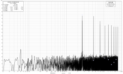
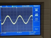
The bad news: I am no more stable in terms of distortion. In fact, it seems to be worse. The second harmonic is nearly 1:1 with the fundamental, and the third and subsequent harmonics are very close behind.
I've attached screenshots of my FFT results and my scope display, in the interest of providing more information.
The good news: I can now reach ~140 ohm on the output control before the lamp illuminates.
The bad news: I am no more stable in terms of distortion. In fact, it seems to be worse. The second harmonic is nearly 1:1 with the fundamental, and the third and subsequent harmonics are very close behind.
I've attached screenshots of my FFT results and my scope display, in the interest of providing more information.
Attachments
- Home
- Design & Build
- Equipment & Tools
- Trying to reduce distortion on an old Heathkit IG-72 signal generator