I was going to snip out the tiny caps in series with the line level inputs as well but forgot when I was replacing the coupling caps which as you mentioned have a considerable impact on sound quality. Did you find replacing the cathode bypass caps to be worth the effort?
I'd definitely do the first caps (short or replace). Any offset that arrives there will affect the 6n3 but stop at the first coupling cap, so I just shorted them.
I thought the sound was better with the new bypass caps and their 0.68s on there, a little cleaner. It needs a CCS though - in both stages.
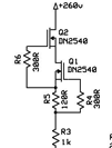
Attached is the CCS that SY uses in his Masters Noise phono amp, it uses DN2540A devices I think - good up to 400V. The attached is 20mA, I need about 5mA for the ECC82 and about 2.6mA for the 6N3 so the 120R resistor needs increasing in the CCS circuit attached. The 1k resistor makes a handy current check too.
After the CCS (We need to make 4 of them) are installed the cathode res + bypass can be removed and replaced with a LED combination to give 2.6V ish for the 6N3 and 8.5V for the ECC82 - adjusted to give a good midpoint to the ECC82 cathode and a reasonablish one for the 6N3. This mod should half the distortion of each stage.
NOTE: The feedback electro needs to be inserted backwards on the board - the markings are wrong (but the build was correct - I need to swap mine back) - as the PCB is +ve with respect to the FB which is at ground.
Attachments
Nice work Globulator!
Using a CCS load for the driver could improve the sound. Judging by your progress so far, I guess it is not long before we will know.
The CCS load will give lower distortion in the driver, but not necessarily lower on the speaker output since the 2'nd harmonic from driver and output tubes will cancel each other to some degree. Also keep in mind that the AC loadline will not be completely horizontal even with a CCS, since there is still the load of the output tubes grid-leak (bias supply) of about 100K.
A CCS load of the input tube will probably not be worthwhile for distortion purpose. THD here will in any case be only abolut 0.1% at max volume.
Since there is already more than enough gain, I suggest to try removing the cathode bypass cap for the input.
The feedback resistor value will have change if you want the same feedback ratio without cathode bypass and/or lower gain driver tube. You could also try to remove the global feedback completely.
You mention an electrolytic cap in the feedback loop. I can not see that on the diagram. If it is connected from output transformer in series with the feedback resistor I suggest it be removed and replaced by a piece of blank wire.
SveinB.
Mods to the input stage
Interesting about the CCS, I did not know the driver and output tube had a symbiotic effect!
That'll save me a lot of parts and messing about 😉
I thought about the bias of the 6N3, and tried some LEDs out in there, finding out that below 3mA they do not have much dynamic conductance. I paralleled another 100k to make the anode resistor 50k, and read the 6N3 load lines again. This tube seems happiest at -2V bias, so I picked a couple of green LEDs and used those - I get (on 220Vac input) 346V before the anode resistor, 140V on the plate (= 4.12mA), with 2.16V on the green LEDs.
I also thought about the 220uF feedback coupling cap - it just takes the DC out which yes - is a bit pointless given the toplogy so that went.
The feedback resistor is 2k, the leg resistor is 33R, I plan to add a small stereo pot to the back of the amp (maybe 1k) between the 8ohm output and ground tapping off the wiper as the feedback, so I can choose between 100% normal feedack to zero feedback at will.
Mod II Summary - 6N3 tubes:
So the sound with this new mod is particularly awesome, punchy, clear, neutral, addictive to listen to. Katie Melua (one of the few well recorded CDs today) and Lily Allen sound very very good indeed.
My test input is a iPod Touch plugged into the MP3 input jack and speakers are some old Kef Cantor III units which sound better than they ever have. The Peach is so peachy in fact the only thing on the list now is variable NFB.
Still have no idea why they used two 6N3 tubes - one would have been fine and easier to match, but hey, it's there.
Interesting about the CCS, I did not know the driver and output tube had a symbiotic effect!
That'll save me a lot of parts and messing about 😉
I thought about the bias of the 6N3, and tried some LEDs out in there, finding out that below 3mA they do not have much dynamic conductance. I paralleled another 100k to make the anode resistor 50k, and read the 6N3 load lines again. This tube seems happiest at -2V bias, so I picked a couple of green LEDs and used those - I get (on 220Vac input) 346V before the anode resistor, 140V on the plate (= 4.12mA), with 2.16V on the green LEDs.
I also thought about the 220uF feedback coupling cap - it just takes the DC out which yes - is a bit pointless given the toplogy so that went.
The feedback resistor is 2k, the leg resistor is 33R, I plan to add a small stereo pot to the back of the amp (maybe 1k) between the 8ohm output and ground tapping off the wiper as the feedback, so I can choose between 100% normal feedack to zero feedback at will.
Mod II Summary - 6N3 tubes:
- Change anode resistors to 50k
- Remove 1k cathode resistors
- Replace 220uF cathode cap with green LEDs
- Replace 220uF feedback capacitor with wire
So the sound with this new mod is particularly awesome, punchy, clear, neutral, addictive to listen to. Katie Melua (one of the few well recorded CDs today) and Lily Allen sound very very good indeed.
My test input is a iPod Touch plugged into the MP3 input jack and speakers are some old Kef Cantor III units which sound better than they ever have. The Peach is so peachy in fact the only thing on the list now is variable NFB.
Still have no idea why they used two 6N3 tubes - one would have been fine and easier to match, but hey, it's there.
Attachments

I'm embarrassed to ask but is the 6n3p a necessity at all? Its looking like rain today, I may open the Peach up and perform a few mods, excellent work!
Yes, with a nudge in the right direction this little amp is a gem, the combination of the ECC82 and capacitor change really opened it up.
The 6N3 is a high gain tube so I think it is required, I'm getting another scope next week from a friend so I'll check the signal levels of all stages. With an iPod input at full level I get a good listening level at 1/3rd level of the control so I think the gain is good as it is - I certainly would not want less. It depends on the amount of NFB too of course.. but I may need a bit of that to help the impedance curve of the speakers.
If I put a CCS on that stage it would raise the gain still further I think.
We do however have a spare triode on each channel, just begging to be used for something, I'm just not sure what! It cannot be used as a current source etc as the heater/cathode voltages restrict that, I wondered about just connecting it in parallel but I'd need more current to hit the operating point of a -2V grid, plus the 22uF looks smaller the higher the current drawn.
So a mystery project unless someone fancies building a MM stage on there, or some type of shunt regulator!
Hmm, do you know the output voltage of the ipod? A CD player with an op-amp output stage should be putting out about 2.5v, with my volume set at 1/3 I get what most would consider loud but tolerable music from a CD source and ~94db speakers. I come from a mechanical background so I'm a staunch believer in KISS, if a robust signal source is sufficient enough for the 6n1p (6n6p in my case) to drive the GU50's via a bypass at the selector then it might be interesting to try it,however I may be daydreaming too.
if a robust signal source is sufficient enough for the 6n1p (6n6p in my case) to drive the GU50's
I think you can try this by soldering a couple of 0.1 caps to the grid (stopper) of the driver stage!
I can't see how it would be near enough however - but that's just my feeling!
Sorry I can't measure signal levels until I get a scope next week!
Are there any similar power tube SE amps with only one other (triode) gain stage? Otherwise a pentode may be good enough on it's own perhaps..
With the original 6N1p driver tube you would require close to 2V RMS for full output power, without feedback.
With the 6N6p you will need close to 3V RMS.
Not practical unless you have a high output preamp.
There are some two stage amps with 300B, which has about the same drive requirements as the triode connected GU50. They are operated without feedback, and use a high gain input/driver tube.
SveinB
With the 6N6p you will need close to 3V RMS.
Not practical unless you have a high output preamp.
There are some two stage amps with 300B, which has about the same drive requirements as the triode connected GU50. They are operated without feedback, and use a high gain input/driver tube.
SveinB
Last edited:
I tried bypassing the 6n3p for a day, the gain is obviously significantly lower but sources like a cd player can still be played to fairly uncomfortable levels (if just barely), with a dvd as a source you loose significant gain and you are maxed out at merely appropriate sound levels, swapping the 6n6p out and using the 6n1p increases gain perhaps 3db but at the cost of harshness. The biggest advantage I have seen so far with this 3 tube arrangement is a drastic reduction in noise ( hiss and hum), there is almost none as far as I can tell. Imaging has changed as well, music and sounds no longer appear to emanate from the speakers. If I did not use this amp for dvds I would be able to live with the gain limitations easily even with the 6n6p, but dvd playback makes it a tough call. I do not recall seeing negative feedback at the amp output, have I missed something?
I think I need the volume then, did it sound better?
BTW I haven't heard a single bit of hiss or hum from mine - perhaps the ECC82 helps there?
For negative feedback look carefully at the 8/4ohm impedance switch at the back, and the shielded wires running under the PSU board - that's NFB from the 8ohm tap.
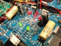
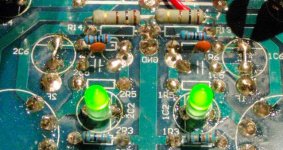
In the attached photo I'm name the FB components (right side only - some text is mirrored on the PCB):
1F - the wire from the 8ohm tap arrives here
1C6 - 220uF series capacitor with 1R6
1R6 - 2k resistor forming upper part of bridge
1C5 - tiny cap straight from 8 ohm tap to bridge centre (RF/stability)
1R3 - 33 ohm from GND to bridge centre - lower part of NFB bridge
Incidental components (this is an old photo as it will match yours better)
1C2 - 220uF bypass cap
1R5 - 1k cathode resistor
R13 - filament balance to ground
So I want a control at the back (1k stereo pots are hard to find though) so I can send anywhere from the designed amount of NFB to none.
Any ideas about the two spare triodes yet? They are bugging me!!
BTW I haven't heard a single bit of hiss or hum from mine - perhaps the ECC82 helps there?
For negative feedback look carefully at the 8/4ohm impedance switch at the back, and the shielded wires running under the PSU board - that's NFB from the 8ohm tap.
In the attached photo I'm name the FB components (right side only - some text is mirrored on the PCB):
1F - the wire from the 8ohm tap arrives here
1C6 - 220uF series capacitor with 1R6
1R6 - 2k resistor forming upper part of bridge
1C5 - tiny cap straight from 8 ohm tap to bridge centre (RF/stability)
1R3 - 33 ohm from GND to bridge centre - lower part of NFB bridge
Incidental components (this is an old photo as it will match yours better)
1C2 - 220uF bypass cap
1R5 - 1k cathode resistor
R13 - filament balance to ground
So I want a control at the back (1k stereo pots are hard to find though) so I can send anywhere from the designed amount of NFB to none.
Any ideas about the two spare triodes yet? They are bugging me!!
Attachments
Last edited:
It would probably be better to bypass and have a listen yourself because sound can be so subjective. I think it sounds great, transparent and very smooth..like I said very subjective. I'm not sure what was wrong with my hearing yesterday, may have been the sandblasting, but gain seems ample now even on dvds with the 6n6p. I plan on checking load lines for the 6n6p to see about seting it up for a little more gain. If the feedback is routed back through the 6n3p then I don't have any as that circuit is completely disabled in my peach.
How did you disable the 6n3? The best way is to pull the tubes I think - then you would cut the NFB and get more gain too.
Perhaps that is the reason it's loud enough now?
I have a scope again now so I'll try to get some level data as I'd like to hook the NFB just around the FU50 stage and perhaps use local around the driver and or input with a cathode resistor without bypass.
Maybe with a 12AT7 or two in parallel I could get all the gain I need in the driver stage with no NFB?
I lifted the grid stopper next to the grid of the 6n6p and connected there, also I just pulled the 6n3p's to get them out of the circuit entirely. I'm on the lookout for a higher gain tube to potentially replace the 6n6p with but I will probably just stick with it as it can handle so much power (4.8w per triode) and it sounds very good.
So I wonder if the improvement you heard was due to the NFB having gone or the 6N3s being taken out? Bear in mind you also remove another capacitor with the stage so perhaps it was a combination of both?
The problem with the driver being both driver and input is one of gain and drive, the combination usually being in pentode territory. For instance my 12AU7 has loads of drive - but not a huge gain.
I wonder if someone can come up with a very high gain driver that is available and works well with 400V? Then we just make a new driver plate with two new sockets and point-to-point wire it in - a big mod but perhaps worthwhile?
What is the FU50 grid like to drive?
OK I have made some measurements with the 'scope in the Sweet Peach. This was based on music however, so it's not very precise - I haven't got a sig-gen!
All measurements are peak-peak and reasonable volume - but are approx.
Input: 100mV
Input to driver stage: 2V
Input to FU50: 20V
I disconnected the FB wires too, and measured
FB wire from 8ohm tap: 5V
FB Bridge = 33/(2000+33) = 0.016 (1/60th)
Connecting the FB gives about 1/2 to 1/3rd the volume.
So there must be in the order of 200x gain to drive the FU50, so if I want to pump the NFB straight into the FU50 I probably need all the level from the 8 ohm tap on the cathode, and still get 1/3rd of the feedback, if that makes sense.
Not sure how to do that though - I could balance the cathode on top of the winding but that would put 60mA though it too... or I could reverse the winding (I.e. switch B+ and the FU50 anode to invert the signal) and feed the signal into the grid with a resistor, still not ideal.
Any ideas?
I tried a little mod tonight that worked quite well, I'm not sure it's better than before but it's certainly no worse so see how it grabs you.
I unsoldered the feedback wire off the driver board, lifted the FU50 10R cathode resistor from ground and connected it to the feedback wire instead (8 ohm tap). I had to add a full turn of each bias pot to restore the FU50 bias back (to 57mA at 220Vac). I want feedback because I want to drive regular speakers - I'm not sure there is enough but it sounded fine. Can't do A/B tests for this. Overall gain went up with this mod.
As there is enough gain on the 6N3s I decided I didn't need the LEDs anymore, so I put back the 1k resistors instead and changed the anode to 100k again. No bypass capacitor needed.
This also gives a tiny bit of local feedback or degeneration as my FB mod removes any feedback from the first two stages. Also a resistor is perfectly linear - I'm sure my LED was good, but not that good 😉
The 6N3s bias is now at 2.4V whereas my target was 2V, but reducing the anode resistor would also reduce the degeneration so I left it.
Next stage is to remove the ECC82 bypass capacitors too, I didn't think of doing that in the workshop but I'll do it next time I'm in there. It's funny to think that I would have eliminated 3 220uF capacitors per channel by then 🙂
I tried an NTC thermister I got from a small blown 50W SMPS in the filament line to the ECC82 to stop the switch on shock, in use it worked fine but also dropped 0.5V and the filament voltage was down to 5.52V. I really need a supply that I can use a resistor with in series to absorb the surge but still allow it to run at 6.3 (or 6.2) volts.
Cathode bias is a good method of feedback, but using the speaker winding in series with the output tube will however give some DC on the speakers which may be undesirable.
I estimate the the global feedback ratio of the stock amp to be about 9dB, and output impedance a little over 2 ohm (depending on the exact characteristics of the OPT).
Without GFB the output impedance will probably be around 4 ohm, which may be OK, but a little more dependent on speakers.
With reduced feedback (due to lower open loop gain with ECC82 or 6N6P) feedback will be 6-7 dB and output impedance somewhere between 2-3 ohm.
The driver tube cathode bypass capacitor should not be required with LED bias. From the photo I thought it was removed already. With cathode resistor it should be left in place in order to have a low impedance drive.
The power-on flash of the Mullard ECC82 is no reason to worry about. It is typical of many European tubes.
Thanks for the input Svein, I think I need to describe the current circuit better!
There is no global feedback now, just the 8 ohm tap feeding into the FU50 10R cathode/bias check resistor.
The driver ecc82 still has a bypass cap.
The input 6N3 now has the 1k cathode resistor. No led and no bypass cap.
Could you tell me how to calculate the feedback in dB? Thanks!
There is no global feedback now, just the 8 ohm tap feeding into the FU50 10R cathode/bias check resistor.
The driver ecc82 still has a bypass cap.
The input 6N3 now has the 1k cathode resistor. No led and no bypass cap.
Could you tell me how to calculate the feedback in dB? Thanks!
NFB
OK I think I may have the NFB calculation down now. It's the amount of reduction in gain caused by the feedback.
So for my case the output stage usually has 20V in to 5V out (counting the FU50+OPT as one block).
This the NFB version I am using has 15V drive going in now (20V - 5V) giving a reduction of 20/15 = 1.33
In voltage dB terms this is 20.log10(1.33) = 2.5dB NFB.
Current sink
As for sending current into the OPT - this works out as:
Speaker load (5.8R - Cantor IIIs), OPT output winding 0.8R.
At 60mA total voltage will be 0.06 x 0.7R = 42mV, giving a current of 7mA through the speaker.
Local FB
I will be removing the cathode bypass cap from the ECC82 next to see what that does - it will degenerate (reduce) the gain and make it more linear, I think the drive for the FU50 will still be strong enough, although I'll listen for any reduction in treble.
OK so as I'm a bit swamped with other things to do I though I'd procrastinate on those and play with my amp a bit more.
I can't say for sure if it sounds better than my ModII stage mods, but it sounds very good with perhaps a little sweeter at the top end, although that may just be a touch less treble or my ears. Until I put a better source through it I'll not really know.
The scheme now is:
6N3 tube with 100k anode load and 2.2k cathode resistor, Vgrid = -4V. This gives is some local degeneration and stays in a good place on the load lines, Vanode is 175V. No bypass caps, no LEDs.
ECC82 with 1.5k (2.2k parallel with 4.7k) cathode resistor. No bypass caps, no LEDs. Vgrid = -6V.
Feedback wires connected to FU50 10R grid resistors. Bias 57mA.
From my Mod II stage I would expect more basic distortion (although maybe not much more as the overall gain is the same) but this moves the feedback to where it is needed - the output stage. The only way of increasing FB (from 2.5dB) here is to have a 16ohm tap or to connect the FU50 in pentode mode, both of which are options but the latter rather easier to try!
However the key with eliminating loop feedback is much lower intermodulation distortion, which is caused by temporal distortion products. I.e. in a regular amp the NFB is too late to correct fully, so the correction itself is corrected - and do it goes round spiralling into the noise floor. Even top amps regularly have the NFB look cover 4-5 stages, which is quite tragic.
This is why local feedback of degeneration was my chosen method - the bias points I chose seem to work out well in the compromise between linearity, drive impedance to the next stage and gain.
I think I need to try it with some decent speakers next - the Usher X-718 which are so much better than the Kefs it's difficult to describe. How they are to drive from my new SET however I have yet to find out 🙂. This step requires domestic integration, which means the base cover on and the amp the right way up again...
Last edited:
- Status
- Not open for further replies.
- Home
- Amplifiers
- Tubes / Valves
- Trying to make sense of the Sweet Peach