I bought pcm58 boards and I am changing the opamps in one of them for opa1611 output.
I planned to use a trimpot of 100k to attenuate the signal. So far so good...
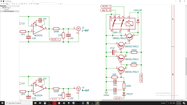
I traced the path of pin6 of output opamp (which is in buffer mode /filter).
The signal goes to the ground,
Then the + of the RCA has a 100R to ground.
Maybe it is late, I cannot figure it out. It must be simple.
It has a relay switches, I tried on and off, no difference.
On the schematic it says 100R in series from Pin6 to + of rca with 10K to ground.
There are the two resistors which both measure 100R, one of them could be the 10K and they are reading in // no clue
I planned to use a trimpot of 100k to attenuate the signal. So far so good...
I traced the path of pin6 of output opamp (which is in buffer mode /filter).
The signal goes to the ground,
Then the + of the RCA has a 100R to ground.
Maybe it is late, I cannot figure it out. It must be simple.
It has a relay switches, I tried on and off, no difference.
On the schematic it says 100R in series from Pin6 to + of rca with 10K to ground.
There are the two resistors which both measure 100R, one of them could be the 10K and they are reading in // no clue
Last edited:
You can't read R values in circuit. 100R reading to ground most likely due to reading through the opamp etc or perhaps through a mute relay that shunts the output to ground.
100k trim pot! Feedback or used as a conventional attenuator? If the latter then the value sounds way to high as it will give poor noise and HF performance. Probably not great as feedback either as it will pick up and add stray noise.
We need to see the circuit.
100k trim pot! Feedback or used as a conventional attenuator? If the latter then the value sounds way to high as it will give poor noise and HF performance. Probably not great as feedback either as it will pick up and add stray noise.
We need to see the circuit.
That is the schematic, however it doesn't match reality. The ground is floating.
I have other values of trimpot to use. I would like to place opa1611 to replace Ne5534 and directly drive my hd650, I know they should be sufficient.
I am planning to place a 15R resistance in series, and a 3K trimpot to ground. Thanks for pointing me the 100k was absurd.
Attachments
I did another set of readings on the dac with opamps removed.
The output of the dac OFF is sent to ground. There is a 200R reading between L/R + s .
And a 100R reading from R+ to Gnd, L+ to Gnd, 100 as well.
The output of the dac OFF is sent to ground. There is a 200R reading between L/R + s .
And a 100R reading from R+ to Gnd, L+ to Gnd, 100 as well.
The circuit you show looks conventional enough but the grounds have to be referenced to 'something'. Digital gear often has separate grounds for digital stuff, analogue stuff and noisy high current servo's and so on. Ultimately though, the audio grounds have to be referenced to the analogue ground part of the DAC chip.
When you connect the outputs to an amp the L and R grounds also connect together via the interconnect leads.
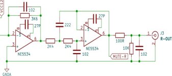
If you use the OPA chip it would be wise to remove the 27pF compensation cap even though the data sheets says no internal connections to those pins.
15 ohm where? and where would the trimmer go? The wiper of the preset should only be loaded with a highish impedance.
The 100 ohm and 1000pF cap form a low pass filter although the -3db point is over 1.5MHz. It will be some form of RF filter to remove extremely high frequency noise and hash.
The final output from the op-amps is shunted to ground when off. That is normal practice and the best way to achieve muting rather than a relay in series with the audio.
When you connect the outputs to an amp the L and R grounds also connect together via the interconnect leads.
If you use the OPA chip it would be wise to remove the 27pF compensation cap even though the data sheets says no internal connections to those pins.
I am planning to place a 15R resistance in series, and a 3K trimpot to ground. Thanks for pointing me the 100k was absurd.
15 ohm where? and where would the trimmer go? The wiper of the preset should only be loaded with a highish impedance.
The 100 ohm and 1000pF cap form a low pass filter although the -3db point is over 1.5MHz. It will be some form of RF filter to remove extremely high frequency noise and hash.
The output of the dac OFF is sent to ground. There is a 200R reading between L/R + s .
And a 100R reading from R+ to Gnd, L+ to Gnd, 100 as well.
The final output from the op-amps is shunted to ground when off. That is normal practice and the best way to achieve muting rather than a relay in series with the audio.
Hi Mooly, I removed the resistors on the board and they are indeed 100R and 10K.
The relay ground the opamp output until voltages are sufficient.
------------------------------------------
Could the output Z of the opamp which is near 0R explains the readings????
------------------------------------------
After reading your posts:
I plan to remove the 1nf
I plan to reduce 100R to 15R to drive directly the headphones or main amp.
The 10K could be replaced with 100K trimpot? which would be in // with the amp trimpot which is also 100K I believe.
My other amp is a tube amp with 100K trimpot then input capacitor to tube grid.
My main amp has a 100k or 50k wiper with 700khz input filter.
Ideally a 3K trimpot would get some volume down for the headphones directly but would be too low and cut bass for the main amps.
With the opamps removed and power off the RCA outputs will read short to ground via the relays.Could the output Z of the opamp which is near 0R explains the readings????
If the trimpot is wired like a normal volume control in place of the 10k then you will get a variable output on the wiper but if you use the wiper to feed headphones then the low Z (300 ohm for the HD650) loading of the 'phones will make the operation of the control very non linear. In other words they will be quiet until the control is almost fully turned up and then all the action will occur in just a few degrees of rotation.
Also 300 ohm 'phones will need more voltage than the common 'phones of lower impedance. Try them first wired directly to the outputs and see if you get enough volume.
Hi Mooly, Powered on with the opamp removed and RCA out disconnected, 100R reads as well as the 10K between GND and +, with the Opamp in place it pulls the voltmeter down draining its voltage sensor and I can only read 99R.
I though about connecting it this way:
Opamp pin6 --- 15R ---- + Out --- Trim pin 1 .
Trimpot pin 2 ---- GND.
One opamp had a bloomy bass in the lowest register, the other was fine with way too much volume. I play with digital 10%.
As I also replaced the first opamp I/V and feedback/cap changed it will also reduce the gain.
Powered on with the opamp removed and RCA out disconnected, 100R reads as well as the 10K between GND and +, with the Opamp in place it pulls the voltmeter down draining its voltage sensor and I can only read 99R.
No need for it to be powered. Small DC voltages can affect ohm reading on the meter.
With power off and opamp removed you should read 100R from pin 6 of opamp to ground.
When the relay is open (not muted) you will read 100R + 10K (so 10100 ohms) to ground from pin 6.
I'm sure there is not a problem with the muting or the values.
I though about connecting it this way:
Opamp pin6 --- 15R ---- + Out --- Trim pin 1 .
Trimpot pin 2 ---- GND.
Its not going to work. The impedance values are all wrong I'm afraid.
Yep, everything reads in order with the opamp removed. It was pulling my voltmeter down in the readings.
with 15R in series and a 300R headphone, at 4VPP it dissipates roughly 6 mW,
I am not sure how this work as the output Z of the opamp is very low and I bump it to 15R is good enough to drive anything.
with 15R in series and a 300R headphone, at 4VPP it dissipates roughly 6 mW,
I am not sure how this work as the output Z of the opamp is very low and I bump it to 15R is good enough to drive anything.
A lot depends on the efficiency of the headphones as well. Ultimately you will only know by trying whether the single opamp can drive them and whether the voltage swing is enough to get the levels you want.
I am trying right now hd650, I just received them this morning to replace my old ones.
Looks like it sounds as it should with ne5532...
Looks like it sounds as it should with ne5532...
The bass is on the verge of too boomy, but there is also too much, that is why reducgin the resistor would help.
Removing the cap and the 10 as well. What would be nice is to bias the opamp in constant current out.
Removing the cap and the 10 as well. What would be nice is to bias the opamp in constant current out.
The problem is that pcm58 is 1mA out, which translate to 9Vpp, way too much, at 5% digital volume it is blasting in headphones.

Well you could try this...
I assume the input to the first opamp is from the DAC and the opamp is used as an I/V convertor. It looks very 'text book' in design.
This is a Philips DAC output stage from a CD150 player. Similar circuit. Note the gain at 64db. That gain gives 2 volts rms output (the CD standard):


If you lower the resistor you lower the gain. This is 270 ohm:


You can go all the way down to 0 ohms so try it and see if it gives the effect you want.
I assume the input to the first opamp is from the DAC and the opamp is used as an I/V convertor. It looks very 'text book' in design.
This is a Philips DAC output stage from a CD150 player. Similar circuit. Note the gain at 64db. That gain gives 2 volts rms output (the CD standard):
If you lower the resistor you lower the gain. This is 270 ohm:
You can go all the way down to 0 ohms so try it and see if it gives the effect you want.
- Home
- Source & Line
- Digital Source
- trying to figure out... Chinese board output opamp trying to figure out...