john65b said:
I stand corrected...The TA3020 is more a Driver than a amp module like the UCD...
Looking to better compare the two Amp modules...
I think the multichannel amp you have does use the TA3020 to directly drive speakers not?
The 5 channel TA3020 I have does have FETS. I just do not remember what they are...
You can barely see them between the heatsink underneath and the PCB...
http://www.diyaudio.com/forums/showthread.php?postid=1076943#post1076943
You can barely see them between the heatsink underneath and the PCB...
http://www.diyaudio.com/forums/showthread.php?postid=1076943#post1076943
TA3020
Hi there, V-bro,
Did you look at those IR Mosfets IRF6785MTR1PBF that can be used with a BBM of 0ns ? i want to order some, for a later board that is, because the package style of these things is far from suitable
here the link:
https://ec.irf.com/v6/en/US/adirect/ir?cmd=catProductDetailFrame&productID=IRF6785MTR1PBF
They are quite strange mosfets, and parts express sells them for around 3¬4 USD per one at low QTY.
Hot-plate, hot air, cold air 
A TA3020 with DirectFET's sounds mojo!
(From AN-1035,
Rework guidelines
Modern rework stations for ball grid array and leadless
packages often use two heating stages. The first heats
the substrate, either with a conventional hot-plate or a
hot-air system. The second stage uses a hot-air
system for localized heating, often with the option of
unheated air for faster cooling of the solder
interconnections on the replaced device; this improves
the solder grain structure.)
v-bro said:
-traces towards the fets are EXTREMELY short.
BTW, say there will be room for air core inductors. 🙂
Air core inductors?
I think I have found THE site for you here:
http://www.kosmic.us/access-acousticrevive.html
Joking...
Really aircore inductors have much better specs for anything under 20Khz, but to filter RF (up to 1,2Mhz in the case of a Tripath amp) it is absolutely much preferred to use something with a core to keep the EMI within boundaries. It is true that these inductors have a great influence on the audio quality, but don't just speculate that what's good for speaker filters is good for this task.
The inductors that are used on the design I am working on are custom value fully shielded dual inductors like the ones on several 41hz amps...but not SMD...
So there could be room for tweaking...there are two inductors in series per side, so there is room for one big one as well 🙂
The amp is VERY alive and kicking by the way! Not far away from a release now!
v-bro said:Air core inductors?
I think I have found THE site for you here:
http://www.kosmic.us/access-acousticrevive.html
Joking...
Really aircore inductors have much better specs for anything under 20Khz, but to filter RF (up to 1,2Mhz in the case of a Tripath amp) it is absolutely much preferred to use something with a core to keep the EMI within boundaries. It is true that these inductors have a great influence on the audio quality, but don't just speculate that what's good for speaker filters is good for this task.
The inductors that are used on the design I am working on are custom value fully shielded dual inductors like the ones on several 41hz amps...but not SMD...
So there could be room for tweaking...there are two inductors in series per side, so there is room for one big one as well 🙂
The amp is VERY alive and kicking by the way! Not far away from a release now!
Sounds good. *Note to self, find a good reason (when the house practically already is full of Tripath stuff) to buy into these 😀
I have this idea that wrapping the inductors in carbon fiber cloth might dampen and disperse much of the EMF.
How about a DirectFET version. 🙂
Or silk 😀 Have you seen that on the bottom of the page that opens on that link? 😀😀😀 Absolutely hilarious!
I am VERY thinking of designing something with directfets! They just look too promising, plus I am still willing to bring the BBM timing down to lower than 80. So far that has never been possible due to overshoots...
I am VERY thinking of designing something with directfets! They just look too promising, plus I am still willing to bring the BBM timing down to lower than 80. So far that has never been possible due to overshoots...
Photo's of the TA3020
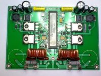
Hey there Guy's
I think i we will not make any further changes to the PCB, so i will now post the photo's of the board, also i can pick up the coils today so all is looking real good.
have a look and let me know what you think.
Arjen
Hey there Guy's
I think i we will not make any further changes to the PCB, so i will now post the photo's of the board, also i can pick up the coils today so all is looking real good.
have a look and let me know what you think.
Arjen
Attachments
Re: Photo's of the TA3020
40! 40! 40! 40! 😀
How about intermittent layers of carbon and silk.
The amp looks good, yet I have two Truepath amps to finish. After that I'm saving up for something with directfets in it, hopefully also using an all-digital signal path.
v-bro said:Or silk 😀 Have you seen that on the bottom of the page that opens on that link? 😀😀😀 Absolutely hilarious!
I am VERY thinking of designing something with directfets! They just look too promising, plus I am still willing to bring the BBM timing down to lower than 80. So far that has never been possible due to overshoots...
40! 40! 40! 40! 😀
How about intermittent layers of carbon and silk.
ArjenShenzhen said:Hey there Guy's
I think i we will not make any further changes to the PCB, so i will now post the photo's of the board, also i can pick up the coils today so all is looking real good.
have a look and let me know what you think.
Arjen
The amp looks good, yet I have two Truepath amps to finish. After that I'm saving up for something with directfets in it, hopefully also using an all-digital signal path.
Tru path
Ive tested the PCB at 40ns, and its not overheating at low power ( say 100 watts ) so i think it should not be a problem.
the direct fets look cool ill ask my friend if he wants to design something with them, but those parts are a bit expensive, and hard to solder. im sure i can find a way around it, but it might take a couple of months.
Greetings,
Arjen Helder
ArjenShenzhen said:Ive tested the PCB at 40ns, and its not overheating at low power ( say 100 watts ) so i think it should not be a problem.
the direct fets look cool ill ask my friend if he wants to design something with them, but those parts are a bit expensive, and hard to solder. im sure i can find a way around it, but it might take a couple of months.
Greetings,
Arjen Helder
Best of luck, in particular with the direct fet project, should you go ahead with it 🙂
Is the BBM set by jumpers?
BBM
The BBM is the Brake Before Make timing,
If you have a H bridge, you dont want all mosfets to be switched on at the same time, because that means you short the rail voltage to ground, and blow up your mosfets.
Therefore, its better to make sure that just before one mosfet wants to switch on, the other one is properly switched off.
There fore they made the BBM timing, 40 or 80 or 120 milli seconds before one switches on and the other switches off to make sure there are no Shoot thrue currents that could damage the parts.
This means also that the eventual PWM wave form looks a bit different with a different BBM and the sound is also influenced by this, be it not very much. The PCB we designed has a minimum BBM of 40nS, but if you would use special mosfets, a BBM of 0 or no delay at all can be reached. this is more expensive in components and these components are very hard to solder, but its not impossible. IR has these mosfets and call's them DirectFET.
Hope that explains it to you.
Hi Arjen,
This looks like your board?
http://connexelectronic.com/product...ducts_id/54?osCsid=eqi6833a78e13b2i810bp0rqu2
Maybe I will get one after all 😀
cheers,
col.
This looks like your board?
http://connexelectronic.com/product...ducts_id/54?osCsid=eqi6833a78e13b2i810bp0rqu2
Maybe I will get one after all 😀
cheers,
col.
- Status
- Not open for further replies.
- Home
- Vendor's Bazaar
- Truepath TA3020