The most easy schematic to see about current feedback is "Alexander Feedback" power amp. It has been discussed in this site as well.
As the feed back goes to the emitors, it is not current feed back. Remember, there are 3 ways to use transistor, common emitor, common collector and common base.
Look at 1 of this front end transistors, the signal fed to base resulting inverted signal in its collector. Now look at this same transistors, there are signal fed from its emitors (like common base operation). Consider yourself in the collector. This signal from the emitors are in phase, while the signal from base are out of phase. They cancel each other, this is what differential is all about, so the gain factor is held steady.
This can be done in 2 way. One is already here in the schematic (signal via base, feedback via emitors), other way is by using differential (signal via base and feed back via base of other transistor)
lumanauw said:The most easy schematic to see about current feedback is "Alexander Feedback" power amp. It has been discussed in this site as well.
As the feed back goes to the emitors, it is not current feed back. Remember, there are 3 ways to use transistor, common emitor, common collector and common base.
Look at 1 of this front end transistors, the signal fed to base resulting inverted signal in its collector. Now look at this same transistors, there are signal fed from its emitors (like common base operation). Consider yourself in the collector. This signal from the emitors are in phase, while the signal from base are out of phase. They cancel each other, this is what differential is all about, so the gain factor is held steady.
This can be done in 2 way. One is already here in the schematic (signal via base, feedback via emitors), other way is by using differential (signal via base and feed back via base of other transistor)
Please write to National Semiconductor, Texas Instruments,
Intersil and others and tell them how it really is and that
they don't have a clue what they are talking about. 😉
Before doing so, you may wish to read the app notes I referred
to earlier in this thread and also study the schematics in the
datasheets for som CFB op amps such as LM6172.
No, this design is current feedback (in the contemporary meaning of the term), it's just an appallingly bad design.
I suggest the 'designer' takes a good look at the 'Alexander' ap-note on the Analog Devices web site to see how to go about things properly.
For example, the dc output offset on the design being discussed here will be all over the place.
I suggest the 'designer' takes a good look at the 'Alexander' ap-note on the Analog Devices web site to see how to go about things properly.
For example, the dc output offset on the design being discussed here will be all over the place.
Correction of my previous post (too late to edit).
I meant LM6181. (LM6172 is VFB, although internally it is a
CFB op amp with a buffer on the negative input AFAIK).
I meant LM6181. (LM6172 is VFB, although internally it is a
CFB op amp with a buffer on the negative input AFAIK).
CFBamp REVISITED

This the updated version of CFBamp
Full detail will be posted until the final prototyping will completed!
 NOTE:Some Diyers here, donot understand the concept of Current Feedback, therefore I request them to please update their knowledge.
Regarding the Alexander CFBamp
The feedback is also applied to output of Opamp which inturns are the emitters of internal output transistors in opamp itself.
This the updated version of CFBamp
Full detail will be posted until the final prototyping will completed!
NOTE:Some Diyers here, donot understand the concept of Current Feedback, therefore I request them to please update their knowledge.Regarding the Alexander CFBamp
The feedback is also applied to output of Opamp which inturns are the emitters of internal output transistors in opamp itself.
Attachments

Re: CFBamp REVISITED
I think you have trouble reading the posts of Christer and others, or maybe you didn't take the trouble to read them.
It is not the "some DIY don't understand etc". It seems you have the disadvantage of being new to this. CF is a term being used for many 10's of years, and means a feedback which is a measure of the (load) current. This was clear until some opamp manufacturers made opamps where the feedback is returned to a low-impedance node. Pressed by their marketing department, they used the term "current feedback"for this. Apparently, you are using this also, you may never have heard it in the original meaning.
That is all understandable, but I would hope you would refrain from telling other people that they don't understand things. As Christer said, yhere is a lot in this world that many of us, including you, are not even aware of. Some modesty goes a long way.
Jan Didden
Some comments on your amp: has this been built or only simulated, or only drawn? Why the large emitter resistors in the input stage? They make the feedback less effective and the performance worse. Why the low 5.6k at the input? Makes it harder for the preamp to give a good quality signal to the poweramp.
amp_man_1 said::
I think you have trouble reading the posts of Christer and others, or maybe you didn't take the trouble to read them.
It is not the "some DIY don't understand etc". It seems you have the disadvantage of being new to this. CF is a term being used for many 10's of years, and means a feedback which is a measure of the (load) current. This was clear until some opamp manufacturers made opamps where the feedback is returned to a low-impedance node. Pressed by their marketing department, they used the term "current feedback"for this. Apparently, you are using this also, you may never have heard it in the original meaning.
That is all understandable, but I would hope you would refrain from telling other people that they don't understand things. As Christer said, yhere is a lot in this world that many of us, including you, are not even aware of. Some modesty goes a long way.
Jan Didden
Some comments on your amp: has this been built or only simulated, or only drawn? Why the large emitter resistors in the input stage? They make the feedback less effective and the performance worse. Why the low 5.6k at the input? Makes it harder for the preamp to give a good quality signal to the poweramp.
Quick, someone go get NP, AKSA, Peter Daniel and all the other movers and shakers!ashok said:We are waiting with bated breath.
I'm so thrilled I just wet my pants.

Just to show that the term "current feedback" still seems to
have different contradictory meanings, the US patent office
seems to define current feedback in the old way. At least that
is how I interpret their definition of subclass 105 of the class
of patent applications regarding amplifiers.
http://www.uspto.gov/go/taf/moc/330.htm
Not that I bother much about what they think since they (and
probably many other countries patent offices) have often shown
ignorance of basic textbook knowledge when granting patents
etc. However, in this case, they do follow the textbookd, ie.
the old ones at least.
However, I found this by searching the internet for the term
"current feedback" and it was otherwise very difficult to come
up with any documents using this definition. Basically everything
I found used the "modern" meaning of the term.
Reply
Hey jannemann u were wrong with the assumption that I neglect or doesnot pay attention to CHRISTER's posts. INFACT I think Christer understand my amplifier in much a better way from all of u.
Secondly,I have updated the amp and the portotype is completed in MATERIALISTIC REALITY , NOT IN VIRTUAL REALITY.
THe regret is only that I have no digital camera to take the photos and post them to show u.
THIRDLY, THE company named ACCUPHASE Labs has also used this type of current feedback topology in their amps such as PX-600E and take a look at their manual also.
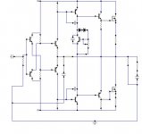
Mr amp_man have you checked my school example of a current feedback amp? The difference is that I use cascodes.
An externally hosted image should be here but it was not working when we last tested it.
Reply
MR. P-e-r-a-n-d-e-r-s SIR I have check ur schematic .
I think u wanna say that my amp is not a current feedback amp
CFB AMP REVISITED BY HEADPHONE AMP MANIAC
MR. P-e-r-a-n-d-e-r-s SIR I have check ur schematic .
I think u wanna say that my amp is not a current feedback amp
CFB AMP REVISITED BY HEADPHONE AMP MANIAC
Re: Reply
I did not say you DID negelect to read Christers post, I said you either did not understand it or you did not read it. Since you now say you read it, the conclusion is clear.
Now you say you built the amp, but you already posted detailed specs (power, slew rate, THD) at your 2nd post. Since the diagrams you posted in posts 1, 2, 23, 45 have such a glaring stupid error that it would never work, I wonder maybe those specs only exist in your head? (If you haven't spotted it yet, let me know and I will explain it to you). In other words, I think you just lied.
Secondly, you irritate many of us and waste our bandwith with your neurotic use of smileys.
Thirdly, you accuse many of us of being too stupid to understand CF.
Are you planning more contributions to this forum?
Jan Didden
amp_man_1 said:Hey jannemann u were wrong with the assumption that I neglect or doesnot pay attention to CHRISTER's posts. INFACT I think Christer understand my amplifier in much a better way from all of u.
Secondly,I have updated the amp and the portotype is completed in MATERIALISTIC REALITY , NOT IN VIRTUAL REALITY.
THe regret is only that I have no digital camera to take the photos and post them to show u.
THIRDLY, THE company named ACCUPHASE Labs has also used this type of current feedback topology in their amps such as PX-600E and take a look at their manual also.
I did not say you DID negelect to read Christers post, I said you either did not understand it or you did not read it. Since you now say you read it, the conclusion is clear.
Now you say you built the amp, but you already posted detailed specs (power, slew rate, THD) at your 2nd post. Since the diagrams you posted in posts 1, 2, 23, 45 have such a glaring stupid error that it would never work, I wonder maybe those specs only exist in your head? (If you haven't spotted it yet, let me know and I will explain it to you). In other words, I think you just lied.
Secondly, you irritate many of us and waste our bandwith with your neurotic use of smileys.
Thirdly, you accuse many of us of being too stupid to understand CF.
Are you planning more contributions to this forum?
Jan Didden
Mr amp_man, you aren't so good in understanding, no? I said in my post that your amp is like mine which is a current feedback => Your amp is also a current feedback.
Mister, your amp is current feedback (of classical design also!) BUT some values of your parts aren't optimal.
1 You input feeds buzz from the supply voltage directly to the input
2 The emitter resistors of the input transistors have a strong influence of speed and stability(?). Should be as low as possible.
3 The feedback cap of 22 pF is a dead sin according to theory. Creates an unwanted peak.
Why don't you fool around with my simulation files and test!
Attachments
Re: Reply
THIS WILL NOT WORK! Get serious man!
Jan Didden
amp_man_1 said:AS i HAVE already stated that i have updated the circuit take a look at this!
IF u think mine is Current Feedback amp then why all other diyers states that this is not a current feedback amp!
THIS WILL NOT WORK! Get serious man!
Jan Didden
Hi peranders, Combattants,
Wheras the benefical aspects of cascoding the outputs
of the diamond are clear, I would assume that the carefully
cascoded current sources setting the bias current are
unnecessary?
I am far from criticizing such a succesfull design, and
putting 10 more standard small-signal transistors in,
doesn't qualify for 'over-engineered' nowadays.
But for the sake of getting more insight: do you
have measured or simulated data to show different
performance of resistor vs simple current source vs
cascaded current source?
Regards,
Peter Jacobi
peranders said:[...] The difference is that I use cascodes.
Wheras the benefical aspects of cascoding the outputs
of the diamond are clear, I would assume that the carefully
cascoded current sources setting the bias current are
unnecessary?
I am far from criticizing such a succesfull design, and
putting 10 more standard small-signal transistors in,
doesn't qualify for 'over-engineered' nowadays.
But for the sake of getting more insight: do you
have measured or simulated data to show different
performance of resistor vs simple current source vs
cascaded current source?
Regards,
Peter Jacobi
Your last question, I don't know!
Still you feed noise from the power supply directly into the input. But I'll guess this isn't important because you achieve 0.00012% at full power, amazing!
Still you feed noise from the power supply directly into the input. But I'll guess this isn't important because you achieve 0.00012% at full power, amazing!
Reply
SO u think all the time i have wasted to reply this thread is just for fun with no reality!
SO u think all the time i have wasted to reply this thread is just for fun with no reality!
Current sources with cascodes creates high output impedance , possibility to lower distortion. How much lower? I don't know at the moment. But if Linear tech uses it I'll guess that there is some meaning with it. Why waste valuable silicon space?pjacobi said:But for the sake of getting more insight: do you
have measured or simulated data to show different
performance of resistor vs simple current source vs
cascaded current source?
You can take my simulation and play!
- Status
- Not open for further replies.
- Home
- Amplifiers
- Solid State
- True Current Feedback N-channel Mosfet Amp