Chris, yes, i was talking about sims, maybe he didn't set bias correctly there. As in real world, too low bias in sims will generate horrible distortions.
Mike
Mike
Hi Mike,
I have never simulated a circuit. My design goes something like this ....
I build something that kind of works, then optimize it. That may take a while.
-Chris
No way! You mean sims sometimes agree with real life??! 😱As in real world, too low bias in sims will generate horrible distortions.
I have never simulated a circuit. My design goes something like this ....
I build something that kind of works, then optimize it. That may take a while.
-Chris
anatech said:No way! You mean sims sometimes agree with real life??! 😱
Yes, sims aren't that bad... If you don't use mosfets at high speeds (ClassD for example, here only scoping gets you further)
Of course real world measurings are always necessary...
Mike

Less talk, more solder and listen 😉
If I imagine how much time people waste here chating . ... 😕
If I imagine how much time people waste here chating . ... 😕
But chatting is so much fun ! 
Anyway, i am sitting here staring onto the layout and thinking about the inductive coupling of the half waves...
I did some math/sims and was able to reproduce quite exact the harmonic spectrum measured. It perfectly fits my theory and will give a distortion rise with 6db/octave. Even the relative amounts / pattern of the harmonics perfectly fit, resulting in the assumption that symasym could do 0.001% in real world with proper layout.
I didn't know that layout is even more difficult than designing amplifier circuit.
Mike
Just remember ... when we spoke about distortion measurement results.
Now the only prove is to produce, setup and measure the new PCB. Who?? Worth doing?
Now the only prove is to produce, setup and measure the new PCB. Who?? Worth doing?
Hi Pavel,
I can build the prototype. I just need to sort out making boards again.
-Chris
I'm in full agreement with you.From the results often seen here, I can recall that wrong wiring overkills PCB merits ....
I can build the prototype. I just need to sort out making boards again.
-Chris
I completely rewired the whole thing, using consequently star grounding. The result was only that i can now measure directly with soundcard and stereoseparation increased to >80db. No change in THD... (but no more fancy spectral lines)
It bugs me seeing that performance of symasym is limited that much by board layout.
Mike
It bugs me seeing that performance of symasym is limited that much by board layout.
Mike
Hi Mike,
Layout has always been the "magic". You know that by now as well as anyone. We can't simulate that yet unless you want to take an RF viewpoint. That will keep you busy.
-Chris
Layout has always been the "magic". You know that by now as well as anyone. We can't simulate that yet unless you want to take an RF viewpoint. That will keep you busy.
-Chris
Mike,
what's your 50Hz suppression? If not about -100dB, then you are wired wrong, and you influence distortion by wrong wiring.
what's your 50Hz suppression? If not about -100dB, then you are wired wrong, and you influence distortion by wrong wiring.
There's not much difference between supply rail induced distortion caused by wrong PCB layout or wrong wiring.
PMA said:Mike,
what's your 50Hz suppression? If not about -100dB, then you are wired wrong, and you influence distortion by wrong wiring.
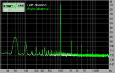
Pavel, it's far from perfect, most of the 50hz junk is captured by RCA-cables, they are too long. (have not enough left right now, they are ~2m each)
But much better, above 1khz is practically nothing left.
I got the soundcard to a level where it does not show any harmonics at all, all harmonics visible are from symasym. (still jfet version)
These harmonics scale linear with impedance of load. (reducing dummy load by factor 5 reduces thd by factor 5)
The peak at 17khz seems to be an issue from RMAA, spectralab does not show it.
Mike
Attachments
mike,
I have a problem - the output stage bias is 1.6mA! I am thinking that this may have something to do with the BD139 (yes, I got a working model). How do you set it? What should be the correct Ib or Vbe? I have messed with it but I can't get the Vbe to go over 570mV. I probably should have asked someone to check my schematic before I started messing with stuff.
I have a problem - the output stage bias is 1.6mA! I am thinking that this may have something to do with the BD139 (yes, I got a working model). How do you set it? What should be the correct Ib or Vbe? I have messed with it but I can't get the Vbe to go over 570mV. I probably should have asked someone to check my schematic before I started messing with stuff.
Keantoken, i do not use bd139 because of that issue. I used bd135 instead, a model that was supplied with spice and works.
For sims you can use practically any npn here, like bc546 of 2n5551.
Sims are not interested in the casing of a bjt.
Mike
For sims you can use practically any npn here, like bc546 of 2n5551.
Sims are not interested in the casing of a bjt.
Mike
So the BD139 is just being used because of the casing (as in more heat tolerance?)? What should be the ideal setting for the POT? I would read the original thread, but it's kind of boring reading something that you barely understand 🙄 . I have recently coughed up an old circuit idea and figured out a way to generate odd harmonics. Could something like this be used in the output stage to cancel odd harmonics? It's really simple:
Two transistors, PNP and NPN. They are joined at the base and the emitter of the NPN is connected to the negative rail and the emitter of the PNP is connected to the positive rail, the collectors being connected to the opposite rails as the emitters. I connected a signal source in series with the supply, and the voltage was distorted. I don't remember about the current, but I am wondering if this idea can be used to cancel harmonics.
Two transistors, PNP and NPN. They are joined at the base and the emitter of the NPN is connected to the negative rail and the emitter of the PNP is connected to the positive rail, the collectors being connected to the opposite rails as the emitters. I connected a signal source in series with the supply, and the voltage was distorted. I don't remember about the current, but I am wondering if this idea can be used to cancel harmonics.
anatech said:We can't simulate that yet unless you want to take an RF viewpoint.
Hi Chris,
Yes you can, to some extent - if you bother to put the resistive/inductive/capacitive properties of the board... perhaps use the transmission line model to interconnect the parts?? It's a bother though...
Cheers
Clem
Yes you can, to some extent - if you bother to put the resistive/inductive/capacitive properties of the board... perhaps use the transmission line model to interconnect the parts?? It's a bother though...
Hey guys!
Think it would be worth it if I tried to make a simple model that would generate noise and implement parasitic properties into circuits in LTSpice? I think that I could do it if someone could tell me what values to use...
I am thinking that maybe the symbol could be semi-invisible and stretches 1 gridpoint per symbol so that it could be used in series to connect parts farther away from each other while accurately adding properties and such. I haver never touched the arbitrary voltage/current sources before, think that these could be used as a form of noise production?
I hope that this is something that I am capable of...
A problem would be layout, though. You would have to arrange the circuit as if it were the PCB...
Maybe someone could request a EMI/RFI LTSpice directive...
Could someone tell me how to make a noise generating circuit with some high-noise transistors such as 2N3904/06? Would amplifying the output of a CCS using noisy transistors work?
- Status
- Not open for further replies.
- Home
- Amplifiers
- Solid State
- Troubleshooting your Symasym