You can check the last option (PH2) by measuring with your ohmmeter between the tip of the red rca connector and the junction R24, C13 and C14.
That's a lot easier.
If there is no continuity, check the solder joints and the pcb tracks.
That's a lot easier.
If there is no continuity, check the solder joints and the pcb tracks.
I hear some clicking/interference when I attach a wire to the R25/C14/C15 junction, but the clicking/interference seems to get quieter when I touch the wire.
Measured 213 ohms between tip of red RCA plug and chassis ground. This seems low to me. Is this lower than expected?
I'll order a new C13. May as well order new C14 and C15 caps just in case.
A few questions about capacitors:
Thanks again for all the assistance! I'm learning a lot.
Measured 213 ohms between tip of red RCA plug and chassis ground. This seems low to me. Is this lower than expected?
I'll order a new C13. May as well order new C14 and C15 caps just in case.
A few questions about capacitors:
- 2n2 means 2.2 nF (and 22n means 22nf), right?
- What kind of non-polarized caps do you recommend?
- What is your preferred source for onesie-twosie components? Tayda?
Thanks again for all the assistance! I'm learning a lot.
Are you sure your meter wasn't telling you 213k rather than 213 ohms? I'd be more suspicious of that misread or of a 220 ohm resistor installed wher that 220k belongs before I'd think that cap was gone to 200 ohms.
And expectations? Look at the schematic. The only DC path to ground is R24, so I expect a reading of whatever R24 might be. Says 220k, but is it? If the color code SAYS 220k, then unsolder and lift one end and measure it again. If the color codes says something else, than that may be the problem.
besides, if you think C13 is the problem, then simply unsolder one end and lift it from the circuit. Now it either has reverb or the problem still exists, and you will know about C13. Whatever tonal contribution it is there for, that doesn't matter for the test. if it gets loud without it, that tells you it was the cause of the issue.
If you replace it, just find a similar film cap. remember, this is just the reverb return, and all it does it roll off some excess brightness and squashes any radio statins it tries to receive.
I don't buy one or two parts. If I have to order, I make up a complete list, and then see what other parts the shop might need, then I order it from one place.
But please don't order a new C13until you actually make the test and KNOW it is bad.
Enzo is right.
The problem with most diy'rs is that they change components to fast.
Before you order any component, you have to be sure it's defective.
Therefore you follow a certain plan in trouble shooting.
As Enzo said, check R24 again as said and desolder C13.
Replacing with other exotic parts to "improve" the sound is the absolute last thing to do.
Usually it's not worth the effort and the money.
It is after all a Guitar amplifier, not a hifi amp.
So back to the solder iron and redo the tests.
Good luck
i still think the "red" rca cable has a short across it.
does injecting a signal at the fx return jack make it to the speaker?(are the solder joints on the fx send and return jacks ok)
and i follow the concensus replacing parts without finding the fault is not the way to go.
does injecting a signal at the fx return jack make it to the speaker?(are the solder joints on the fx send and return jacks ok)
and i follow the concensus replacing parts without finding the fault is not the way to go.
Swapping out parts that maybe bad, or maybe don't sound as good as they could, is a good way to start a parts bin. Because maybe they're good. Then next time, if you need a spare, you have a good sporting chance of fishing a good one out of the bin. Because maybe those spares aren't going to fry whatever circuit you plant them in. And just think of all the time and money you'll save, not having to wait for parts to come in. Plus they're free.
Just don't mix up the used parts with new ones. I hate going to the parts bin and finding questionable used parts. Then again, you're not me.
Just don't mix up the used parts with new ones. I hate going to the parts bin and finding questionable used parts. Then again, you're not me.
Great advice guys. I'll desolder a leg of C13 and check whether the reverb returns, then desolder a leg of R24 and check its resistance.
Turk I believe I have sound through the speaker when playing through the effects return jack, but I will double check.
Just to be clear, I should check the resistance from the tip of the red RCA plug to ground with the amp powered up (to charge the capacitors), correct?
Turk I believe I have sound through the speaker when playing through the effects return jack, but I will double check.
Just to be clear, I should check the resistance from the tip of the red RCA plug to ground with the amp powered up (to charge the capacitors), correct?
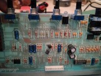
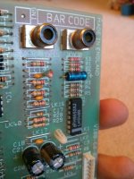
Finally had a chance to put some time into this. Went to desolder C13 and had a fun surprise: C13 had been replaced by a 222 ohm resistor (see attached photo). I guess that's where the 213 ohm resistance between the tip of the red RCA plug and chassis ground came from. I should've seen that earlier. In my defense, some component names are hidden under the components 🙂
Clipped one end of the impostor C13 resistor and checked for reverb. Still have the same issue: no reverb on either channel. No buzz when I touch the tip of the red RCA I do hear crackling when I rotate the clean reverb control knob.
I also looked around the circuit a little more and noticed a few more instances of replaced components (see C42-45 of attached photo).
But as Enzo said, there must be another issue, correct? Otherwise the reverb should have returned when I clipped C13.
Attachments
Post 57, 58 - Test of rca cable.
Let's go back a few steps due to the new findings with "C13".
Check if the red rca cable is fine. Measure continuety between the tip and the wire end at the pcb side.
Recheck the junctions of C14/C15/R25.
Touch with a screwdriver if you have a buzz at:
pin 12 - IC1
The junction mentioned above
The connector PH2.
Of course, you have to mount the pcb back in to the chassis and power it up.
No need to fix all the potentiometer nuts or these from the jacks. Just a few so the pcb will not "fall" in to the chassis.
There are these 3 or 4 plastic pcb holders; click them into the pcb.
Reconnect the ac wires if you disconnected them.
Come back with the results.
I know it's a lot of work; but that's the only way to find out what can be wrong.
This is the less interesting part of repairing amps. Dismounting the pcbs, replacing parts, mounting everything back, find another problem, dismounting etccc... You get the picture...
"C13" is out of the way, whatever it was it is not needed for the circuit to function.
Isolate the problem. When you touch that tip, is ther signal at pin 14 of IC1d? If feeds pin 6 of the ribbon to the main board. It might clear the op amp, but not make it through the ribbon. Over on the main board, you report turning the controls makes noise, so IC2 ther probably works. Touch pins 2 or 7 with something metal and see if noise results.
Isolate the problem. When you touch that tip, is ther signal at pin 14 of IC1d? If feeds pin 6 of the ribbon to the main board. It might clear the op amp, but not make it through the ribbon. Over on the main board, you report turning the controls makes noise, so IC2 ther probably works. Touch pins 2 or 7 with something metal and see if noise results.
Checked signal using signal trace on reverb circuit with the following results:
Signal tracer was grounded to chassis ground. Does this narrow the problem down to the reverb tank itself? The tank measures 300 ohms across the "in" (black) jack and 200 ohms across the "out" (red) jack. Resistance measurements taken with tank removed from circuit.
- There is signal on the tip of PH1 (black RCA plug) inside reverb tank
- There is NO signal (only fuzz) on the tip of PH2 (red RCA plug) inside reverb tank
Signal tracer was grounded to chassis ground. Does this narrow the problem down to the reverb tank itself? The tank measures 300 ohms across the "in" (black) jack and 200 ohms across the "out" (red) jack. Resistance measurements taken with tank removed from circuit.
Without reading 75 posts to refresh my memory, the plug into the OUTPUT jack on the reverb pan is the return. The return is a high gain amplifier stage. if you pull that plug out of the pan and touch the tip of it with your finger, there should be substantial hum out your speaker. If there is, then the return circuit is working. If not, then the return circuit is dead. Wasn't that where the whole C13 was?
I have no idea which color cable went where. But the cable plugged into the INPUT jack on the pan is the drive. If you get signal there, it probably is working.
Continuity through the two end of the pan - your 200 and 300 ohms qualifies - means it is likely OK.
You won't detect a lot of signal on the output end of the pan because it is a low level signal. If you shake the pan and hear spring clatter out the speaker, the return is working.
if there's no input there won't be any output.Checked signal using signal trace on reverb circuit with the following results:
- There is signal on the tip of PH1 (black RCA plug) inside reverb tank
- There is NO signal (only fuzz) on the tip of PH2 (red RCA plug) inside reverb tank
Signal tracer was grounded to chassis ground. Does this narrow the problem down to the reverb tank itself? The tank measures 300 ohms across the "in" (black) jack and 200 ohms across the "out" (red) jack. Resistance measurements taken with tank removed from circuit.
did you ever confirm that the low voltage rails are correct seems to me you reported strange voltage readings(pre regulator if i'm not mistaken)that could be of concern here.
if there's no input there won't be any output.
did you ever confirm that the low voltage rails are correct seems to me you reported strange voltage readings(pre regulator if i'm not mistaken)that could be of concern here.
There IS input to the reverb tank, when sending a tone into the amp input I can pick up the signal at the reverb tank input.
- Status
- Not open for further replies.
- Home
- Live Sound
- Instruments and Amps
- Troubleshooting Marshall VS100 without powering up?