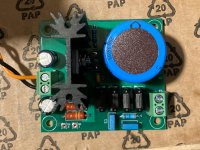
This board will do 6.3 D.C.from 6.3 A.C. and it is small.
DIY PCB Board - Tube Amp - LV Tube Heater DC Power Supply - 6.3VDC from 6.3VAC | eBay
DIY PCB Board - Tube Amp - LV Tube Heater DC Power Supply - 6.3VDC from 6.3VAC | eBay
IIRC, you haven't yet received the parts you wanted to elevate the heater supply. That might be enough by itself. Or maybe I'm just wishing on a star. All good fortune.
Ps: Thanks very much for turning me on to the Quasimodo thread - hadn't seen it.
Ps: Thanks very much for turning me on to the Quasimodo thread - hadn't seen it.
Last edited:
I found in my parts bin a 150K 2W resistor, 47K resistor and 100uF 100V cap, so I did try elevating to 75V and it did not make a difference unfortunately.
Even though DC heaters solve the issue and I'm fine with that solution, there is still a missing piece for me.
Since the ringing was not present with the iPhone, I am fairly confident that AC running on the PCB traces is not the problem.
So perhaps this is indeed some ground issue with the 6.3 VAC center tap connected to ground and that somehow getting through the pot?
When I used DC, I grounded the 0V DC side, not the AC center-tap.
Last edited:
A different take is that the ringing spikes were still present on the heater line when driven by the iPhone, but weren't coupled (nearly as much) into the high impedance of the grids because of the very low Z of the iPhone's outputs.
Another view of the remaining noise when B+ transformer secondary is roughly snubbed, and raw AC to heaters, is that the snubbing isn't yet optimized. AC *should not* make any special extra noises if it's only heating the heaters (except possible hum). From this point of view, except for possible hum, AC should behave the same as DC, provided the AC is mains frequency only. Ergo, there's still spiky noise on the heater line.
Another view of the remaining noise when B+ transformer secondary is roughly snubbed, and raw AC to heaters, is that the snubbing isn't yet optimized. AC *should not* make any special extra noises if it's only heating the heaters (except possible hum). From this point of view, except for possible hum, AC should behave the same as DC, provided the AC is mains frequency only. Ergo, there's still spiky noise on the heater line.
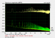
I ran the spectrum analyzer on the amp with volume pot maxed out, with no signal.
- AC heater vs. DC heater
- AC heater (w/ HT snubbed) vs. DC heater
It is easy to notice the noise differences, both objectively and subjectively.
Snubbing the HT cleaned up the AC heaters quite a bit, but the amp was still noisier than DC.
That said, I am fairly certain that the transformer made less mechanical noise, so I want to make the HT snubber permanent.
I got LA vol.5 and read Jones article, the text on page 25 is not entirely clear to me.
For the center-tapped transformer, are dual RC snubbers needed, or just a single one across the two secondary leads?
I generally prefer the Quasimodo C-RC snubbers, but they are a bit hard to fit in the current PCB layout I have.
Attachments

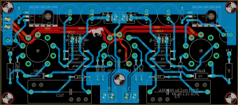
Since I'm going to order the heater reg board PCB, and most of the cost is shipping, I was thinking of trying a newer version of the PCB where the left input trace is moved farther from the heater.
Any thoughts on this change? While I'm at it, any other suggestions?
Any thoughts on this change? While I'm at it, any other suggestions?
Attachments
try to series a 1K resistor before INR and INL, and add a weak positive voltage +50V on heater pins
Crap. Went away for a minute and everything I'd typed is gone. "That's not a bug, it's a feature."
I'd think that because the ringing happens separately and at different times in each HV secondary half, that separate dampers would work better, and not rely on the transformer's internal coupling. Cuts the capacitor voltage requirement in half, so not a total burden.
I'm still concerned that your HV ringing damping isn't optimum. Zero is a very big number, but should be approachable. Nothing I've yet read has given a simple "cookbook" solution for an R and a C that probably works in a particular situation. Should be doable, but haven't seen it yet. Until then, Jones suggests an RC pair that will serve. And remember, the resistor does the damping, the cap's only there to unburden the resistor.
If you aren't yet committed to DC heaters, you might explore some high frequency filtering in an AC heater line instead, on the theory that *that's* what the DC heater supply is actually doing. Maybe some combination of CLC? Depends what's in the junkbox.
All good fortune,
Chris
Sorry about that! Maybe you need to check the "keep me logged in" option.
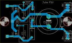
I have the Quasimodo test jig and measured the optimum R with 10nF and 150nF snubbers, it was about 1.2K
This is a draft PCB to replace the one I have there now.... for adding a snubber for each half.
I like the regulated DC heaters because out of the wall I currently have 7VAC, so atleast I know that will be a constant safe voltage for the tubes.
Attachments
It would be great for all of us if you could document the noise voltage on your heater lines without, and with, optimum HV snubbing.
How do you begin the Quasimodo process? Do you pick a capacitance and then dial in the resistor value? But how do you pick the capacitance? Or two, for the Johnson C-RC.
7VAC! Yikes. Around here I've seen 130 volt mains in new neighborhoods, before all the houses come on line. Even century old downtown nieghborhoods can have over 125 volts. It's becoming a real issue for DIYers, and has been for a while for restorers of antiques.
YOS,
Chris
It would be great for all of us if you could document the noise voltage on your heater lines without, and with, optimum HV snubbing.
Will do. I'll order the PCB's together, first I'll replace the PSU with snubbing and test again with AC. Then I'll incorporate the DC heaters.
How do you begin the Quasimodo process? Do you pick a capacitance and then dial in the resistor value? But how do you pick the capacitance? Or two, for the Johnson C-RC.
Everything is documented really well in the PDF attached on the first post of that thread. The tl;dr is that you start with a default value of Cx=10nF and Cs=150nF. Attach the secondary to the test jig and short the others. Once the resonance is displayed on the scope, you turn a removable 1k trim pot until it is optimally damped. Remove the pot and measure it for optimal Rs.
7VAC! Yikes. Around here I've seen 130 volt mains in new neighborhoods, before all the houses come on line. Even century old downtown nieghborhoods can have over 125 volts. It's becoming a real issue for DIYers, and has been for a while for restorers of antiques.
It's not entirely surprising in this case. The PT is a Hammond 270HX, 550VCT for HT and 6.3VCT @ 6A. Primaries are either 115V or 125V.
The optimal HT for the Maida reg in my case is 590VCT, so I used the 115V primary.
Combine that with only 1.8A needed on the 6A tap, it is fairly high.
But I guess that will be an advantage for regulated DC.
Thanks very much for pointing me at the pdf. I'd skipped over it after reading the dreaded letters "SMD" somewhere and broken into a cold sweat. It's wonderfully clear and well written - better (for my level of knowledge) than his LA article, which is great, but difficult to gnaw through.
In the pdf, Johnson gives good reasons for his choice of capacitors, with an unspoken emphasis on solid-state voltage and therefore impedance levels, but enough that we could extrapolate from there. I'd guess just scaling linearly with voltage would be close enough? Voltage varies linearly with turns, and leakage inductance and stray capacitance are each (maybe?) very roughly linear with turns, so... Still wishing for a more "cookbook" answer someday.
Have two issues with his process though. First, he assumes the primary is fed from zero Ohms, even at high frequencies. This just can't be close enough.
And second, he adjusts for critical damping and then stops. Why? What's so special about critical damping? Why not just overdamp and call it a day? The damping resistor will get a little hotter, but what other defect would occur? He doesn't even show curves for overdamped, so there must be some reason, but I don't know it.
Thanks again,
Chris
Excellent questions that I have no chance of answering!
But, I'm sure that if you post them in the Quasimodo thread he'll address each one of them 🙂
But, I'm sure that if you post them in the Quasimodo thread he'll address each one of them 🙂
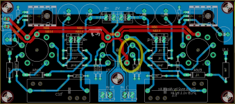
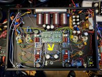
This might have been mentioned - I didn't read the entire thread, but when I had this issue (oscillation/noise in the middle of the pot) it was oscillation and fixed by running shielded signal wiring (I had originally just used UTP), and then using the scope/headphones to route the wire where the problem stopped.
The wire with the yellow arrow in this photo - if I route it on the other side of the caps, it creates noise on that channel. The tube in that socket is an STR75/60 VR tube, but removing that tube didn't effect the noise. Only by routing the wire across the board instead of around it did I fix the issue.
The wire with the yellow arrow in this photo - if I route it on the other side of the caps, it creates noise on that channel. The tube in that socket is an STR75/60 VR tube, but removing that tube didn't effect the noise. Only by routing the wire across the board instead of around it did I fix the issue.
Attachments
Crap. Went away for a minute and everything I'd typed is gone. "That's not a bug, it's a feature."
Whenever I type a long winded post, I select all. Then if the forum pulls that crap I just paste it into the new message. Alternatively if I know it's gonna be a long message when I start it, I'll write it in gedit or (notepad if I was on Windows and paste it when I'm done.
All the boards are in and I was able to conduct a few tests ..updates:
1) Properly snubbing the HT did not help eliminate the noise entirely... but it looks really solid and I'm happy to keep it there.
2) The heater boards work really well. With the 6.3VAC tap, fully loaded there is about
8VDC on the main filter cap, and a steady 6.1V on the output, as configured.
3) The new boards that route the signal wire around the heater are absolutely silent with AC 😱
So the issue was the PC board all along.... as some folks recommended earlier, I performed a small bit of surgery and cut the heater trace that goes down to pin 9, and jumpered it off board. With that mod, the previous board is quiet too.
Attachments

- Home
- Amplifiers
- Tubes / Valves
- Troubleshoot noise in tube-amp, volume pot dependent