Yes, if there is noise on the heater supply it will try to couple to anything nearby. Much like young men! The spiky (therefore wideband) stuff couples well through even small capacitances to high impedance points, so eliminating the spikes at their source seems the best plan of attack.
YOS,
Chris
YOS,
Chris
Okay I made some progress, and the latest info seem to be relevant.
First, I replaced the entire PCB with another one I had, and the same exact issue appeared, so atleast I ruled out any faulty parts like the coupling capacitors.
Next, I played with a variety of caps across HT secondary --
0.1uF -- too high, introduces lots of noise
330pF -- too low, does nothing
0.01uF -- some progress.... spikes are gone! I may be imagining it but I feel like the PT is buzzing a bit louder. Also feels like more hum with volume pot maxed out, although this isn't a real issue as 1/4th of the pot is sufficient volume.
Is 0.01uF good or is there a better values in this case?
Chris, I've read Mark Johnsons article about rectifier ringing in LA 10 and have the Quasimodo which I used for a Pearl 2 PSU.... but did not consider for the tube amp.
Referring to that article, differences between diodes can be significant.
Initially, I used a MUR460 in this amp (due to the excellent performance in that article), but it got destroyed since the PIV was not sufficient. That lead to a debugging thread before this one:
Help troubleshoot tube PSU ... blowing fuse
To replace those, I used a 1N5408 which I had on hand.. I wonder if replacing those diodes may improve the ringing.
You'll want to read Morgan Jones' article in Vol.5 then. The upshot is that even a crude guesstimate at snubbers across the transformer's secondary solves all issues. And that snubbers or capacitors across the rectifier are mistaken - essential reading.
Might want to try some resistance in series with your cap - maybe a K Ohm or so - to damp the leakage inductance better. All good fortune.
Might want to try some resistance in series with your cap - maybe a K Ohm or so - to damp the leakage inductance better. All good fortune.
Thanks for the extra tips, I'll give that article a read.
This noise was always present on the left channel, regardless of what I did.
I'm thinking that heater trace next to pin 6 is the culprit. As mentioned earlier, the ringing did not appear on the scope on the grid of the input tube, but was present at the plate, which is pin 6 right by that trace.
I'm still puzzled why there the noise did not exist when the input was shorted, if indeed the issue is capacitive coupling to from the heater trace to that pin
Are you certain that you could actually *see* the spiky noise at the grid in the presence of the noise from the 1M resistor? Whatever's there would be amplified by the valve and at a lower impedance at pin 6 - well, you get my drift.
Oh good point... I think that would make sense as the noise wasn’t present with the iPhone as source either so I don’t the board routing is at fault here
If you have no issue at all using an iPhone then it still can be ground related. As the iPhone had no ground. Please check your mains ground loop as well.
Yes agreed, although I don’t know what else to check/ change with regards to the ground.
I just finished another extensive round of testing and while the 0.1uF eliminates the nasty buzz, the amp is not as quiet as with the iPhone. Therre is still some vageuly audible noise
I just finished another extensive round of testing and while the 0.1uF eliminates the nasty buzz, the amp is not as quiet as with the iPhone. Therre is still some vageuly audible noise
You maybe able to connect a couple of caps from each side of the heater supply to ground. I have never done this maybe 1uF. You would need to connect to your star ground point and make sure this return does not get into the signal ground. I don't know if this will help. When the input is shorted the grid has zero impedance to ground so no noise. If you imagine 2pF from you heater wire and 50K to ground that's is what you are seeing. If are happy to pull off a track you could cut the offending heater trace (at both ends) and wire. There are quite a few threads where buzz has been this issue. Sorry cannot offer a complete solution. The other option is just to run that first valve off DC but again the DC supply must be clean.
Last edited:
Yes the buzz from the transformer may change. Its due to the sudden collapse of the current when the diodes turn off. The buzz can also change as the transformer warms up. Check the bell housing too.
An snubber comprised of an RC of 1k and .001uF covers secondary voltage ranges from high to low (according to a Morgan Jones).
Not to beat a dead horse, but did you cut the vias and run the heater on the outside of the board with properly twisted wire on the bad channel?
Not to beat a dead horse, but did you cut the vias and run the heater on the outside of the board with properly twisted wire on the bad channel?
Just disconnect the green wire for testing purpose from the star ground.
I did this earlier and the noise was much worse
If you imagine 2pF from you heater wire and 50K to ground that's is what you are seeing. If are happy to pull off a track you could cut the offending heater trace (at both ends) and wire.
An snubber comprised of an RC of 1k and .001uF covers secondary voltage ranges from high to low (according to a Morgan Jones).
Not to beat a dead horse, but did you cut the vias and run the heater on the outside of the board with properly twisted wire on the bad channel?
I want to try everything possible before physically damaging the board.
Next up I will try:
1) RC snubber
2) A different power transformer
3) Power the heaters AC from a separate transformer
4) Power the heaters DC with an adequate PSU
5) Different pot, 20K or 25K
 I have the parts for all of the above tests. Will find some time within the next few hours to try it
Okay some better progress here.
- AC heaters from separate toroidal transformer -- no spikes but still some background noise. Again, this is likely a non-issue with speakers, but with headphones noticeable
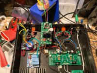
- DC heaters from separate toroidal -- reg outputs 6.3VDC, dead quiet background.... issue resolved from my perspective.
- DC heaters from 6.3VAC tap -- same quiet background. Issue though is that I'm only getting 5.8VDC from the reg. The 6.3 winding is rated at 6A (PT is Hammond 270HX) so I don't think that is the issue.
The diodes there are ISL9R860P2 so I think they may have too high of a forward voltage drop.
Either way, I don't want to use this board in my build, its too big and it snubs each individual diode.
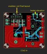
I have a draft PCB for DC heaters with the same MIC29502WT LDO.
This board is more compact, uses a large snap-in cap and will incorporate quasimodo based CRC snubber instead of the cap per diode. I think I'll finalize this PCB and this will be the long-term solution.
Amp should be nice when its done!!
- AC heaters from separate toroidal transformer -- no spikes but still some background noise. Again, this is likely a non-issue with speakers, but with headphones noticeable
- DC heaters from separate toroidal -- reg outputs 6.3VDC, dead quiet background.... issue resolved from my perspective.
- DC heaters from 6.3VAC tap -- same quiet background
. Issue though is that I'm only getting 5.8VDC from the reg. The 6.3 winding is rated at 6A (PT is Hammond 270HX) so I don't think that is the issue.The diodes there are ISL9R860P2 so I think they may have too high of a forward voltage drop.
Either way, I don't want to use this board in my build, its too big and it snubs each individual diode.
I have a draft PCB for DC heaters with the same MIC29502WT LDO.
This board is more compact, uses a large snap-in cap and will incorporate quasimodo based CRC snubber instead of the cap per diode. I think I'll finalize this PCB and this will be the long-term solution.
Amp should be nice when its done!!
Attachments
Sounds like your on the case. Difficult to get 6v3 DC from 6v3 AC. AS you said need LDO reg, you can also use Schottky diodes for bridge.
- DC heaters from 6.3VAC tap -- same quiet background
The diodes there are ISL9R860P2 so I think they may have too high of a forward voltage drop.
I wonder if you'd have enough voltage if the DC was only used for the driver valve? Could be tested by pulling the output valves temporarily. On third thought, maybe not a true enough test.
YOS,
Chris
Last edited:
Yes I'd certainly have enough DC for only the driver, but that would require butchering the PCB and I don't want to do that as of yet.
That said, there should be enough for the whole amp.
Each EL84 is 750mA, and the 12AT7 is 300mA. Total of 1.8A AC
Rectified to DC requires 3.6A.
The PT is rated at 6A so I think that should be more than enough headroom.
The MIC29502WT has a dropout voltage of 350mV at 4A, so I would only need 6.65V DC from the 6.3VAC tap, or even 6.3VDC and lower the DC to 6V which is fine too.
I think the issue here specifically is that the diodes I used in the PCB have a rather high forward voltage drop.. should have used Schottkys
- Home
- Amplifiers
- Tubes / Valves
- Troubleshoot noise in tube-amp, volume pot dependent