I'm trying to fix above Cambridge Audio CD player.
The initial issue was the CD tray not opening/closing normally. The whole mechanism has been replaced and now works perfectly.
The next issue is quite puzzling, at least to me, not being an expert in this field.
The digital output works fine.
The analog output sounds like a 'bathroom', output is lower and appears to be distorted frequency-dependent. Also, it feels like the sound is not in phase. I.e. using a Hifi News Test Disc the announcer's voice is not there in analog out, while it is loud and clear in the digital output.
I've read most if not all diyaudio messages related to similar Cambridge Audio players. One issue that came up was with the quality of the capacitors over time. To achieve possible sound improvements and fix the issue the elco's on the DA board were replaced.
No luck.
I’ve verified the voltages on the DA Board are in accordance with the listed voltages in the service manual.
I've not seen any messages on blown DA convertors/opamps, so I'm tempted to exclude that as an option?
I do not have crackling/loss of sound. Both channels appear to misbehave in the same fashion.
I've measured the resistors around the opamps; these seem to measure as expected.
Yet, it would seem to me, as an amateur, the issue must lie somewhere in the summing of L+ L- and R+ R- and filtering/feedback subsequent to the DA convertor?
Can anyone shed some light on this issue?
How to get the core issue? What am I missing here?
Thanks in advance,
Bruno
Attachments
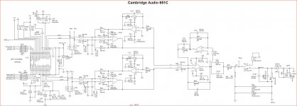
Have a look with a scope at the audio on TP8 through to T11 while using your test disc's 'missing' track. It does sound an oddball fault though.
The analog output sounds like a 'bathroom', output is lower and appears to be distorted frequency-dependent. Also, it feels like the sound is not in phase. I.e. using a Hifi News Test Disc the announcer's voice is not there in analog out, while it is loud and clear in the digital output.
I've read most if not all diyaudio messages related to similar Cambridge Audio players. One issue that came up was with the quality of the capacitors over time. To achieve possible sound improvements and fix the issue the elco's on the DA board were replaced.
That hollow, missing center sound is probably phase inversion... if you have a short on one of the opamp inputs the differential to single ended conversion could fail, inverting one channel and causing the problem.
For each of the caps you replaced, check for shorts or solder bridges. Use the continuity scale on your meter directly across each part, if it beeps or shows a short, you've likely found your problem.
Thank you for your prompt responses.
I just purchased a Hantek Oscilloscope, but have yet to study on how to work with it 🙂.
So, I guess I need to find the "Using Oscilloscope from beginner to advanced" first.
I did measure the DC Voltage on TP8/11 without CD playing and it shows 2.43 V on all test points.
For both measurements my question is: what is to be expected at the test points?
That's exactly the problem. I ran track 2 of the test CD, which deals with channel phasing. The first part of the track is out of phase and can be heard through the analog out. The second part of the track is in phase and result in dead silence for analog out.
As for the shorts caused by capacitor replacements. Yes, but I would need to take the player first. And the issue existed before capacitor replacement. I would like to measure before disassembly.
So I guess, I need a crash course on the use of the oscilloscope and somehow determine if the inversion takes place within the DA convertor? Could that even be the case?
Or should I focus on subsequent opamps? As described in WM8740 output stages in Cambridge Audio 640c mkI vs mkII these appear to deal with combining out of phase inputs.
How can I get sensible measurements around the opamps? I'm not really into SMD (de-) soldering, so how can I verify these stages?
Thanks for all your help so far.
Thank you for your prompt responses.
I just purchased a Hantek Oscilloscope, but have yet to study on how to work with it 🙂.
...
For both measurements my question is: what is to be expected at the test points?
Audio. Those are audio test points where you can actually see and hear the music playing.
That's exactly the problem. I ran track 2 of the test CD, which deals with channel phasing. The first part of the track is out of phase and can be heard through the analog out. The second part of the track is in phase and result in dead silence for analog out.
Is this true for both channels?
What happens if you drive only one channel?
What happens if you drive the other channel?
As for the shorts caused by capacitor replacements. Yes, but I would need to take the player first. And the issue existed before capacitor replacement. I would like to measure before disassembly.
Understood ...
So I guess, I need a crash course on the use of the oscilloscope and somehow determine if the inversion takes place within the DA convertor? Could that even be the case?
Most likely you've got one opamp that's not working correctly.
How can I get sensible measurements around the opamps? I'm not really into SMD (de-) soldering, so how can I verify these stages?
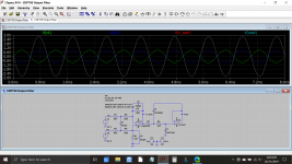
How's your junk parts bin? I just posted a quick and dirty LM386 audio test amplifier schematic in the Solid State Forum... If you're up to a quick and easy build this would help you a lot since you could probe various points in the circuit and actually hear what's going on.
Last edited:
Ok. Is L+ equal to L- except in reverse phase?
What does the circuit behind the test points do?
In the referred message it is stated: "It seems they are using what's basically two "superbal" input stages (Self, Fig. 12) to combine N and P output for each DAC channel, and then another to combine both channels out of phase." Can you explain in layman's terms?
The 2.43V measured is fine?
Yes, it is true for both channels independent of each other. So that would imply it's caused by something shared by both channels or an issue which just happened to occur in each channel independent of each other?
I've tested with different amplifiers/CD players, so I trust the issue is located within the CD player DA section.
The only shared resource is the power supply as far as I can see? Dual Convertors and 3 opamps per channel are used.
The parts bin is pretty much empty except for Black Gates/Panasonics/ELNA's etc. I'm in (re-)startup phase with regards to audio.
Thanks,
Bruno
Ok. Is L+ equal to L- except in reverse phase?
What does the circuit behind the test points do?
In the referred message it is stated: "It seems they are using what's basically two "superbal" input stages (Self, Fig. 12) to combine N and P output for each DAC channel, and then another to combine both channels out of phase." Can you explain in layman's terms?
The 2.43V measured is fine?
Yes, it is true for both channels independent of each other. So that would imply it's caused by something shared by both channels or an issue which just happened to occur in each channel independent of each other?
I've tested with different amplifiers/CD players, so I trust the issue is located within the CD player DA section.
The only shared resource is the power supply as far as I can see? Dual Convertors and 3 opamps per channel are used.
The parts bin is pretty much empty except for Black Gates/Panasonics/ELNA's etc. I'm in (re-)startup phase with regards to audio.
Thanks,
Bruno
To be completely honest, I'm not sure what's going on. It appears, from the schematic, they are using both sides of a stereo DAC chip in each channel, getting two sets of differential signals and combining them into a third differential signal than combining it into a single ended output. It's one of those "Why the hell would they do that?" circuits and I'm not sure I can trouble shoot it without getting it on my bench... and maybe not even then.
I think my best move is to step out and let someone else give you a hand here. Sorry...
I would expect the audio on those test points to be 180 degrees phase shifted, one with respect to the other.
This is a not totally dissimilar circuit from a Sony player and this shows the phase relationships and amplitudes.
When you play a mono test track on your player the two channels should of course show similar phase.
Opamps play by exacting rules and in your circuit I would expect to see ALL pins apart from the supplies to be at near zero volts DC.
Attachments
OK. So I'll familiarize myself with the oscilloscope first and start measuring TP8 through TP11 for the left channel with various test tones to see what shows up.
Thank you both for all your help so far.
Bruno
Thank you both for all your help so far.
Bruno
I've used a test CD with several sine wave (1/5/10 kHz) tracks to measure at various points in the circuit.
At TP8/9/10/11 the same wave form is shown. I see the wave form before and after R44/45. Hardly any signal is found at C57/C52 and TP16.
Question: I do not see any/180 degrees phase shift between TP8/9/10/11? Could that be caused by the measurement process/oscilloscope i.e. me?
At TP8/9/10/11 the same wave form is shown. I see the wave form before and after R44/45. Hardly any signal is found at C57/C52 and TP16.
Question: I do not see any/180 degrees phase shift between TP8/9/10/11? Could that be caused by the measurement process/oscilloscope i.e. me?
Good question 🙂
Yes, the scope will always trigger on the same point of the waveform irrespective of absolute phase compared to another point. You need to use a dual beam or dual trace scope (which most are tbh) and then you will see the phase difference between the traces as both are displayed at the same time.
I'm trying to think whether a single beam would show any phase difference if you used the external trigger option and triggered it from one phase while viewing the other. I'd have to think about that.
I'm doing my best to read, learn and understand to reach enlightenment. One day...
I've purchased the Hantek 2D72 a 2-channel digital oscilloscope. I guess that should work, at least once I receive the 2nd probe?
That aside; given the measurements above wouldn't it be logical to assume the failure is to be found in the circuit behind R44/R45? Also, couldn't I just measure AC V between R44 and R45 to determine whether the signals are in and out of phase?
Once again, thanks for your help.
The fault may very well be after R44/45... and something I've thought of that I should have mentioned at the start is to check that the grounds of the RCA output sockets are OK. If the print is cracked and the ground floating then you would get these symptoms.
Assuming the grounds are OK then we do need to look with the scope at the phase relationship of a mono signal. Given that audio is (in the scheme of things) very low frequency you should be able to use ordinary wire to connect the scope to the circuit.
You could certainly look at the outputs that way and then work forward. For a mono signal each trace should match the other, and if the scope has an 'invert' function for the second channel (which inverts phase) and also an 'add' function (which adds channel 1 and 2) then you should see nothing but a straight line as the two signals (one inverted by the scope) add together.
- Home
- Source & Line
- Digital Source
- Trouble shooting Cambridge Audio 651C