Good for your friend Mitch & his prize winning amps, But your example fails the test in regard the pointsYou can see that even the 811A with just 8dB CFB will get around 2 DF as measured by my friend Michi:
of my original post. In several ways.
The 811A is not a common audio tube. Other than as a PP Class B modulator.
No mention at all in regards Class A operation in the RCA Transmitting Handbook.
There is a short form sheet recently from Amperex on the 811, close enough.
In this cct the 811A is running Class A2, not covered at all in my piece.
Doesn't tell us what % of the signal from the OPT is fed back to the 811A.
The NFB to the input can be set to any degree desired long as phase shift is looked after.
So can be used to push the 811A real hard. Just another way to lower the DF.
None of these factors will change the impedance put in the path of the signal from the 811A to the lautsprecher.
Probably OK amps anyway, they look nice, So long as they don't kill the kat or set the curtains on fire.😀
Don't post it here Osvaldo, start a new thread, that wayThe circuit is actually working but it is in prototype state. Still remains unfinished. Unsure if sometime I'll finish it. I lost my job 3 years ago, and possibly you had listened in TV or radio that Argentina is becoming unlievable because corruption, delinquency and economy. Prices of good duplicates in a year while salaries are of misery (my apologies by the of topic but I need to explain this to justify why it is unconcluded).
It uses about 20 compactron tubes including rectifiers, no one grain of sand beyond the glass of them. I didn't do a schematic mediocrely showable, but I have an ASCII ART one. The positive current feedback is taken via a current transformer. The speaker is coupled via a toroidal autotransformer and the amplifier itself is fully DC coupled.
more people can see your work & benefit from your measurements & observations..😀
👍
Quite a few folks here on DIY seem to have some knowledge or at least opinions with regard to CFB.😀The QUAD had the good solution (CFB) but, IMHO, it's all spoiled by GRND feedback. Pentodes (and tetrodes) that have at least (effective) 5 mA/V mutual conductance (like the EL34 used at 450-500V with 40 mA anode current + 400V for g2, outputting 60 to 75W with 5K p-p load with really low distortion) and used as such with 10% CFB already get a damping factor around 2.5. So this is possible even with class AB amps. If class A with almost 2xgm, higher plate load and CFB between 10-20% it can get really good.
Many people, including those us here on DIY Talk the Talk. But Talk is cheap. Time for some to come forward & Walk the Walk.
Start a new thread covering cathode FB, but back up your opinions with real data. That does take a bit of work.
Let us know why your way is the better way. And prove that with fact.😱
Don't worry. I don't want to contaminate this thread with my foolery.Don't post it here Osvaldo, start a new thread, that way
more people can see your work & benefit from your measurements & observations..😀
👍
Last edited:
Could it be helpful to have a lower DF when hearing at lower levels, and higher DF when hearing at higher levels (EG like UL and triode)?I'm sure you have read The Relationship Between the Power Output Stage and the Loudspeaker in Radiotron Designer's Handbook. Everybody else should too. (The version in RDH 3rd is slightly better, IMHO.)
So that at lower levels we can get a bit more lows (due to the higher impedance) to chase the Fletcher-Munson curve while at higher levels can better control the inertia of the speaker.
It was just a real example that shows what modest CFB does. The 811A has very high plate resistance for being a triode. The DF improves by 10 times and yet the driving voltage is still pretty manageable.. That's all.Good for your friend Mitch & his prize winning amps, But your example fails the test in regard the points
of my original post. In several ways.
The 811A is not a common audio tube. Other than as a PP Class B modulator.
No mention at all in regards Class A operation in the RCA Transmitting Handbook.
There is a short form sheet recently from Amperex on the 811, close enough.
In this cct the 811A is running Class A2, not covered at all in my piece.
Doesn't tell us what % of the signal from the OPT is fed back to the 811A.
The NFB to the input can be set to any degree desired long as phase shift is looked after.
So can be used to push the 811A real hard. Just another way to lower the DF.
None of these factors will change the impedance put in the path of the signal from the 811A to the lautsprecher.
Probably OK amps anyway, they look nice, So long as they don't kill the kat or set the curtains on fire.😀
It does tell what signal is fed back. The CFB winding of that Tango is 36R and that results in 8 dB CFB.
Regarding the necessity of high damping factor to properly drive loudspeakers, I don't think it's a general desirable requirement , At the best it applies to commercial stuff where amps and speakers are designed in certain way.
A tube amp will never behave like constant voltage source no matter how low is it's output resistance. PP Class A SS amplifiers are the only ones that can get very close to the perfect constant voltage source.
Because ALL tube amplifies that employ GRND feedback I have managed to put in use all have the same signature sound: lean, lifeless and boring. I find a well designed cheaper SS amp outperforms them comprehensively. I pick the CFB because I can design and easily get my OPTs but Schade fbk gives the same results.Quite a few folks here on DIY seem to have some knowledge or at least opinions with regard to CFB.😀
Many people, including those us here on DIY Talk the Talk. But Talk is cheap. Time for some to come forward & Walk the Walk.
Start a new thread covering cathode FB, but back up your opinions with real data. That does take a bit of work.
Let us know why your way is the better way. And prove that with fact.😱
A pentode with CFB (or Schade fbk) is effectively behaving like a triode. Or the other way around, there was an old article showing that the triode can be (mathematically) derived from a pentode with internal feedback. Not surprising. Feedback in the real world is everywhere. Just need to use the best type for the job at hand....
Last edited:
Maybe this one. 😀there was an old article showing that the triode can be (mathematically) derived from a pentode with internal feedback.
Attachments


IIRC it was 10% indeed, like I mentioned in the post, even if the tube in pentode and not UL. What I've seen is that every tube reacts very differently.QUAD had a better solution. After some research they found the best degree of CFB that reduced 3H in PP pentode operation.
KT88 with 20% local feedback from plate to grid1 become a very very nice triode, some other tubes like EL84 can live with alot less LNFB.
I remember @Wavebourn has almost all of his amps working with looper feedbacks and one is a controllable positive current feedback to be able to have an amp with negative Zout.I have a project of OTL with 6JN6's combining negative voltage feedback with adjustable positive current feeback.
True, the 811A is not a common audio tube but they did find their way into quite a few audio amps 40 or so years ago before the WWII surplus stash dried up. So did the 813 to a lesser extent, and the 807 still gets audio use despite the fact that it's just a 6L6GA in RF tube clothing.The 811A is not a common audio tube. Other than as a PP Class B modulator.
No mention at all in regards Class A operation in the RCA Transmitting Handbook.
There is a short form sheet recently from Amperex on the 811, close enough.
In this cct the 811A is running Class A2, not covered at all in my piece.
Cathode feedback is build choice or switchable option in my SSE amp. I probably have some measured data from 15+ years ago somewhere on a hard drive. I used an EL34 version in triode mode with no feedback for the typical DHT music where there was often a single singer and a single instrument. Want to slap some speakers around with something complex, loud, or bass heavy, pop in some KT88's crank the bias current up to 100 mA, switch to UL mode, and turn on the CFB. Both the extra current and the CFB make modest improvements in DF while UL squeezes about 14 watts from a 6550 or KT88.
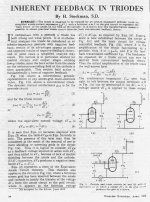
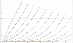
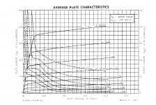
Want to make triodes out of pentodes, add a mosfet follower to feed the cathode and tie a resistor divider from plate to grid to ground. The first picture shows the pentode curves. The second picture shows the converted curves with the same 150 volts on the screen grid. These curves were taken by hand using old analog power supplies and cheap DVM's that's why the spacing isn't exactly perfect.
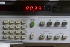
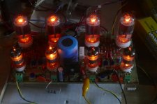
The last 4 pictures show a test amp running two pair of these 6GF5 tubes in "triode mode" for 80 watts at 3% THD. No feedback is applied other than the direct plate to grid local feedback in the output stage. The output impedance was somewhere around 1 to 1.5 ohms and much of that cane from the guitar amp quality OPT's that I use for tests that could end badly. This amp still works though.
Attachments

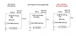
After all the noise, here is another calc of resistance inserted into the audio path by the OPT. One of the original intents of this thread.
This one is the OPT used in the Sims for the 46 46 A2 Amp in the other thread. Looks like ~0.7 R on the 8R lead.
I've been on DIY a few years now, I don't recall anything like this being covered before.
The target efficiency of 85% is met, check the power into the OPT at the final 46 plate vs power out at the load.
This information is primarily for Newbies & Lurkers, And others if they wish.
Not for all the 'Know it Alls' here on DIY. 😀
Attachments
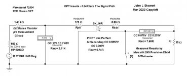
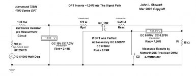
Here then yet another flight into the World of 'Where Are We Now'.
This is a never used Hammond 1700 Series OPT I boght circa 1960. Still in the box with the packing.
These were offered as a good alternative to the Partridge OPT recommended by Williamson for his Amplifier.
The actual voltages & resistances have been measured using a MetraHit 29S precision DMM & Wattmeter.
https://www.gossenmetrawatt.com/english/produkte/metrahit29s.htm
In both calcs & simulations its good to see the estimate of the source resistance is close to the actual numbers for the 200CD & Series R,
I will leave it to the mathematically inclined to check my work. Hope I didn't screw up! 😀
Attachments
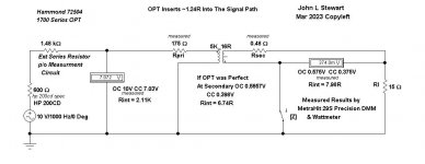
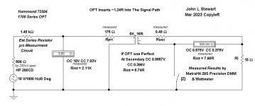
Here are the Sims corrected, the 16Z tap on the Hammond 1700 Series measured 0.48R DC.
The measurement this time is 4-terminal to eliminate lead & contact resistance,
The current source used is a small CC PS I built circa 1970, about 400 mA max.
It is very useful for low resistances & non-linear devices such as diodes. It was run for about an hour to stabilize before measurements.
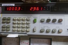
Test current was 206.7 mA, voltage across the 16Z winding was 99.0 mV. So R of the wdg is ~ 0.48 R.
Good to see the Sim calcs are close to the actual measured results. And THX again to gorgon53 for checking my work. 👍
The measurement this time is 4-terminal to eliminate lead & contact resistance,
The current source used is a small CC PS I built circa 1970, about 400 mA max.
It is very useful for low resistances & non-linear devices such as diodes. It was run for about an hour to stabilize before measurements.
Test current was 206.7 mA, voltage across the 16Z winding was 99.0 mV. So R of the wdg is ~ 0.48 R.
Good to see the Sim calcs are close to the actual measured results. And THX again to gorgon53 for checking my work. 👍
Attachments
- Home
- Amplifiers
- Tubes / Valves
- Triodes Have Similar Damping Factors & How the Output Transformer Will Further Reduce That