Please list the other connections, and I will add them to the poll.
Screen drive?
Twin drive?
Inverted mode?
Can anyone think of other topologies?
Unfortunately, only two more modes could be added. My suggestion is to get rid of the switchable options...Triods and UL or triod for penthodes,.... every return back the signal /FB/ press it and deprive sound from air, space,.... linearity is good for modes, but doesnt mean good sounding, IMO. To be technician is not enough...can be and audiophill to sense the sound...
Pentode/Tetrode - with regulated a screen and feedback; short loop. Heck I prefer pentode drivers too.
+1
Inverted triode modes:
I don't see inverted triode N Fdbk to the driver stage listed, although it was mentioned above. (ie., a differential triode driver stage with N Fdbk from output plate, or UL tap, back to the unused triode driver plate) This will require two diffl. driver stages (one for each output tube) for P-P. This gives triode sound, using power pentodes, with low output Z.
Or the similar N Fdbk to diffl. pent. driver screens (crossed Fdbks, esentially P-P driver UL) can do the same/similar with just one diffl driver stage. These all provide full pentode power output with a triode distortion signature and low output Z.
Crazy/Twin and G2 drives are low output tube distortion options for the final output stage for most pentode schemes. But high output Z.
-------------------------------------
Rather than state what is best, here is what is WRONG with most traditional approaches:
CFB: too much HV drive required, but manageable with reduced CFB, special OT required ($$$), but low Zout and distortion at least
UL: N Fdbk path not linear or same as forward path, but lowish Zout (may still need more N-Fdbk), could be fixed up with special screen drive (followers, screen currents returned to plates). Power output and current handling at peaks are reduced from pure pentode (the most serious problem, better to do UL for the driver stage instead, see above inverted ...).
Triode: low power out, expensive tubes, distortion locked in by non-linear N Fdbk unless very lightly loaded (OK if triode sound wanted), not efficient, but low Zout
Pentode: high output Z, non-linear grid 1 transfer, requires additional N Fdbk (Crazy/Twin or G2 drive can fix the non-linear part) But grid 1 easy to drive.
Schade, shunt: requires high current driver so not natural for tubes, but a beefier pentode driver can handle that, or Mosfet followers.
Series Schade is similar to CFB but no special OT needed, interstage xfmr. instead.
Driver-grid N-Fdbks: makes driver input Z low, crossed N-Fdbks pass thru the OT (stability? diffl driver should fix mostly). But very low distortion and low output Z (from higher loop gain).
Driver cathode N-Fdbks: this is CFB for the driver stage, just larger drive signals to the driver stage, which is no big deal at this lower level; HIGH output linearity and low output Z; no crossed N-Fdbks thru OT - so good for stability (except higher loop gain to manage), overall one of the best for LINEAR results, but may sound TOO linear. (suggest the inverted triode scheme variants above for more "natural sound") The RCA 50 Watt handbook amplifier uses this -and- shunt Schade N FDBKs (probably easier to get stable for DIY with the resulting lower loop gain).
Crazy/Twin/G2 drive: requires a HV driver stage with current drive as well, so driver design is the challenge. Gives a Very Linear final output stage, but still high Z out. Requires one of the other N-Fdbk schemes to fix that.
Last edited:
I fully agree with wavebourn . The Shade mode is by far the easiest way to adjust the output impedance . What you are forgetting ,that the output transformer has variable inductance in function with the amplitude and frequency ,it requires to be driven by low impedance source .
CFB: too much HV drive required, but manageable with reduced CFB, special OT required ($$$), but low Zout and distortion at least
As you say moderate CFB, something like 75%-25% partition between plate and cathode respectively, is more than good enough.
The good news is that no special order for OT is required anymore. Toroidy of Poland make PP transformers on good quality toroidal core with 24% CFB (they define CFB with reference to Za instead of turns and it's 10% in such case) with various turn ratios for just under 250 US$ per pair (basic finish). Considering the 80W nominal power and the very good bandwidth it's very good value for money.
The 2K plate-to-plate with 10% Za CFB will make an overall 3.5K total primary impedance which is excellent for a lot of sweep tubes.
The 4K plate-to-plate will make 7K and so on....up to 8K plate-to-plate which will make almost 14K!
I have built just about all of these, and yes, some switchable amps, especially my own SSE's. Is a switchable amp a compromise, yes, and so is just about everything else in life.......
And as with many compromises, sometimes it's just the right choice for the task at hand......Yes, for most music my SSE stays in triode mode without the CFB turned on, but hook up the big speakers and spin some Pink Floyd vinyl, and that UL switch with the CFB turned on IS the right choice.
If I had to pick a favorite mode from this list, it would be totally dependent on what tubes I was using and whether it was a SE or P-P amp.
An SE amp likes triodes....and pentodes with local feedback, and.....
A P-P amp with KT88's or most of the other common audio tubes likes triode or UL, or maybe a good pentode design. If sweep tubes are used, then G1 driven pentode was my mode of choice.....until recently.
I have been working on a "grand unified theory" that makes one mode suitable for all applications and tube choices for several years. I had given up several times, but recently stumbled on a board that I had trashed a few years ago and made it work.....sort of. There is still much work to be done, but there is some hope that it will work out, and it is definitely NOT on this list, so for now I must vote "none of the above."
I like pentodes more then triodes after some builds of this two modes i prefer pentodes it suite my taste better.
I have been working on a "grand unified theory" that makes one mode suitable for all applications and tube choices for several years. I had given up several times, but recently stumbled on a board that I had trashed a few years ago and made it work.....sort of. There is still much work to be done, but there is some hope that it will work out, and it is definitely NOT on this list, so for now I must vote "none of the above."
2 of us...
there is some hope that it will work out, and it is definitely NOT on this list
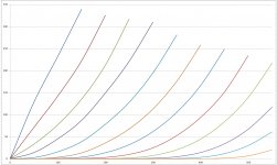
So, what configuration makes curves like these with a 15 watt sweep tube? How many sweep tubes can eat 550 volts in triode? The voltage is only limited by my Fluke 407D power supply.
Note the data behind these curves was generated with old vacuum tube linear power supplies and Harbor Freight meters, then plotted in Excel. The inconsistencies between the left set of green and purple lines are caused by inaccurate voltage settings.
More details to come after I have built a few working amps. So far I have not been too successful with two tubes actually exploding. After shelving the project yet again, I discovered the stupid math error that caused the shattered tubes....pesky decimal point......24 watt tubes (6DQ5) do not like dissipating 200 watts, not even for an instant.
Test amplifier construction is underway.....again.
Attachments
My first guess would be an R divider from plate to cathode driving a Mosfet follower, which in turn drives the screen grid at some % of plate V. A sort of reduced voltage UL mode, looking like a triode, to be compatible with the low screen voltages of TV Sweep tubes.
It would be nice if some way could be found to reduce the rollover of the resulting triode like curves at the HV end.
It would be nice if some way could be found to reduce the rollover of the resulting triode like curves at the HV end.
Of all the amps I've built, I liked PP DHT triode and PP pentode amps with stabilized screen voltages as low as practically possible (and enough feedback to keep output impedance low). My current build uses PPP KT88 with nested feedback loops: CFB to cascode driver cathodes, cascade input stage with NFB from plate of 2nd stage to cathode of first, split load inverter and GNFB to first stage cathode and 270V regulated on the screens. Total feedback around the output stage is 24dB (when loaded with 8 ohms). Admittedly, it is a lot more difficult to stabilize such a design but it's possible and the effort was worth it after listening to the first completed channel.
I call it "The HeretiK" 🙂
I call it "The HeretiK" 🙂
Such "HeretiK" approach is the way to make an amp that is good for any genre. 🙂 An amp for any genre
- Status
- Not open for further replies.
- Home
- Amplifiers
- Tubes / Valves
- Triode, UL or Pentode connection? What do you prefer?