On another thread I posted an aside as a addendum to a otherwise on topic technical contribution:
another poster has gone off topic and is pursuing the throwaway comment about Triodes
so the title is the topic of This thread – is there “negative feedback” built in to triodes – is limited voltage gain, plate resistance a consequence?
I don’t remember where I 1st encountered the idea – is it just a feedback engineer’s “urban legend”?
Many circuits predating the wide-spread adoption of feedback analysis are still usefully analyzed with the more recent intellectual tools - followers, degeneration are taught today as feedback circuit techniques
Anyone interested enough to follow up with references? – if I cared enough I would look at 50’s electronic textbooks as Bode’s work, Blackman’s theorem only became widely distributed after WWII
maybe a start:
...it is hard to not comment on ... several swipes at negative feedback:
use enough closed loop gain in a negative feedback amp with only smooth, low order nonlinearities and you get decreasing levels of harmonic distortion with harmonic order - not the 10-20 dB some "no-feedback" types may tepidly apply - it is easy to have >60 dB loop gain at all audio frequencies
there is no other practical way to obtain useful damping ratios - cathode, source, emitter followers are all 100% (local) negative feedback circuits - there are no "inherently low output impedance" amplifying devices
the "no-feedback" crowd's beloved Triode vacuum tube has loads of internal negative feedback - directly causing the observed plate resistance - a tube without internal feedback is a correctly biased Pentode{emphasis added}
negative feedback is a foundational principle and should be properly understood and used correctly - ignore audiophool mythology if you want to learn how to design sucessful circuits
another poster has gone off topic and is pursuing the throwaway comment about Triodes
so the title is the topic of This thread – is there “negative feedback” built in to triodes – is limited voltage gain, plate resistance a consequence?
I don’t remember where I 1st encountered the idea – is it just a feedback engineer’s “urban legend”?
Many circuits predating the wide-spread adoption of feedback analysis are still usefully analyzed with the more recent intellectual tools - followers, degeneration are taught today as feedback circuit techniques
Anyone interested enough to follow up with references? – if I cared enough I would look at 50’s electronic textbooks as Bode’s work, Blackman’s theorem only became widely distributed after WWII
maybe a start:
..for those still interested in tube theory just try some search: Langmuir-Childs law
Improved vacuum tube models for SPICE, Part 1
basically the Vgc and Vgp voltages control the current via the same nonlinear law
A triode can be modeled as a voltage controlled current source (gm*Vgc) in parallel with the plate resistance (Rp). If the cathode resistance is zero or it is bypasses, then there is no feebdack through Rp. Rp will be in parallel with the anode resistor. If there is a cathode resistor, then Rp could be thought of as providing negative feedback. However, Rp varies with operating point so the feedback in nonlinear for large variation in plate voltage.
another poster has gone off topic and is pursuing the throwaway comment about Triodes
It was me, who "has gone off topic pursuing the throwaway comment". Actually, I reacted on your off-topic comment about triodes as pentodes with feedback, asking the question that you could not answer.
Please try once more... How come that feedback inside of pentode that makes triode eliminates higher order distortions? And, how it may justify application of feedback to other devices where it increases order of distortions?
Uh, the plate produces feedback even if there is no cathode resistor. The figure called Mu gives the ratio of the grid's voltage affect on cathode emission current versus the effect of plate voltage on the cathode current. Individually the plate effect is called Rp (1/Rp = Gm(p) for the plate) and the grid effect is called Gm (1/Gm equiv. to Rg). They both vary non-linearly with current due to the Childs 3/2 power emission law approx.
In practical devices, the grid does not follow the 3/2 power law so well due to grid wire proximity effects at the cathode, square law emission (grid1 effected) might be a better approx. for some high gm tubes and power tubes.
In practical devices, the grid does not follow the 3/2 power law so well due to grid wire proximity effects at the cathode, square law emission (grid1 effected) might be a better approx. for some high gm tubes and power tubes.
Last edited:
Schade Fig 35, go figure...
Conversely, a triode with internal feedback sabotaged: a Pentode.
Most obvious example of the reversed principal at work is Cascode...
Conversely, a triode with internal feedback sabotaged: a Pentode.
Most obvious example of the reversed principal at work is Cascode...
Last edited:
hoping debate can continue in this thread I'm copying this to here
You can't have it both ways.
If triodes have internal feedback, then so do pentodes,
since they exhibit a finite plate impedance due to their
"feedback".
😎
As engineers we can perhaps argue over what defines "good approximation" in terms that make sense to both of us
I am happy to engage in the original meaning "dialectic" - not that I think we really have uniformly "opposing" positions or that every engineering issue can be reduced to simplistic "two sided" sets of propositions with simple binary true/false resolutions
(which doesn't mean that there's no definitions, standards that have to be agreed - and are agreed by the EE community - some statements can be "nonsense" or "true/false" by the rules that a community like professional EEs use to "construct"/express/represent knowledge )
for tube internal feedback we should continue in my thread in the tube forum?
the better measure of internal feedback in vacuum tubes is probably (inverse) "mu" - which is easily 100x higher in pentodes vs triodes
so pentodes would seem to at least qualify as ~ "100x better approximations" to "no (internal) feedback" amplifying devices by having ~100x less internal feedback?
my tube expertise is pretty limited to having been the only one with any idea of how to replace/rebias/maintain a Dynaco tube amp in a community music room in my college days I could easily be wrong – care to put up some numbers to compare or point to some good tube modeling sites?
In one of those life ironies George Valley hung around the undergrad program I was in but before I realized I wanted to do electronics he fully retired
Since my education in control theory started with Mech E courses and my career has involved motion control with a variety of motors, hydraulic valves as well as electronics I do think I can figure out diverse "gain device" parameters if anyone wants to “put some numbers” on the floor to debate
this source kind of fades away before reaching pentode properties: Tubes 201 - How Vacuum Tubes Really Work
so the title is the topic of This thread – is there “negative feedback” built in to triodes – is limited voltage gain, plate resistance a consequence?
I don’t remember where I 1st encountered the idea – is it just a feedback engineer’s “urban legend”?
It's not an "urban legend". It's quite real. Triodes are unique in that the Vpk has a decided effect on plate current. The plate current of a pentode, and the collector/drain current of a transistor are largely independent of the Vpk (Vce, Vds). This is why the parameter (u-factor -- amplification factor) is so useful for triode analysis, but not so useful otherwise.
If the signal is moving Vgk positive, the plate current increases, and the Vpk falls, as a consequence of increased voltage drop across the plate load. The decreased Vpk will therefore try to reduce the plate current.
It works the opposite if the signal voltage is taking Vgk more negative: less plate current, and a rising Vpk that will try to increase plate current.
Vgk and Vpk are pulling in opposite directions, trying to prevent Ip from changing at all, and that is the definition of negative feedback. The effect is largely absent from every other active device, solid state or hollow state.
As for the effectiveness of Vpk in controlling the plate current, that's given by dynamic plate resistance (r(p)). The greatly reduced effectiveness of this sort of plate feedback in the high r(p), low current, low Gm triodes (e.g. 12AX7, 6SF5, to a lesser extent, 6SL7) with their high r(p)'s, tends to make these sound like pentodes, which is why some consider them sonically inferior to the lower-u small signal triodes like the 6SN7 or 6FQ7 (nine-pin mini version of the 6SN7). It's not that you can't make the high gain triodes (or pentodes or transistors) sound good, it's just that it doesn't come quite so easily. You'll have to pay more attention to loadline selection, and, with pents, probably have to do some empirical breadboard tweaking of screen voltages and bias points to find out where the low distortion point really is. Also, pents will probably require added attention to stiffening screen voltages and screen bypassing. You may also have to resort to fully or partially active plate loading.
Hi Jcx,Anyone interested enough to follow up with references?
Sure a triode has internal feedback. The input is not protected from the output.
Here's a reprint from 1953:
stockman
Shows it in terms of classic feedback theory.
As far as no feedback goes, internally the input needs to get protected from the output. Hence the term no feedback. A pentode tries to do this, as well as two cascode connected triodes.
Mike
p.s.
I don't understand why some say cathode/emitter degeneration is not feedback. Just ask the question: Can the output influence the input? Then its feedback!! I know I'm preaching to the choir here.
Last edited:
Yes, of course a triode has internal feedback. However, as it says in post #4, this is not linear feedback but shaped in a similar way to the grid response. Hence an ideal triode in an ideal circuit can have zero distortion with non-zero voltage gain. There are no ideal triodes or ideal circuits, but it is nice to know that at least in theory it works.
Pentodes (and tetrodes) have very little internal feedback. This is because the whole point of introducing g2 was to prevent this feedback from happening. An ideal pentode would have a 3/2 grid law, and infinite output impedance. External negative feedback, such as the anode follower circuit, can reduce distortion (and add higher order components) but it will only get near zero when the gain gets near zero too. This is because the external feedback is linear, so it can only suppress distortion not cancel it as the triode does.
If you define negative feedback as being linear and sampling voltage only then the triode does not use feedback and cathode degeneration is not feedback. This, however, would be a perverse definition of feedback intended to artificially bolster a weak argument. On any normal definition of feedback (sample the output, to affect the input) then triodes and cathode degeneration use feedback. This means that many "zero feedback" circuits work only by adopting a perverse definition of feedback, because some people have an irrational fear of feedback - I suppose we are all afraid of things we don't understand!
I remember this being debated ad nausem on rec.audio.tubes some years ago.
I suggested the following experiment. Wire up a pentode as a triode and measure its stage gain and distortion harmonics at a given frequency and output level.
Next wire up the same pentode as a pentode with NFB so that it has the same stage gain. Again measure the distortion harmonics at the same frequency and output level.
If a triode truly is a pentode with NFB then the results should be at least very similar i.e. the relative levels of the harmonics should be very similar.
In practice they are not.
Cheers
Ian
Those embarrassed by the idea of having hidden feedback in their amplifiers could always look at it another way:
- an ideal triode is a linear voltage amplifier with a non-linear output impedance (so for best results have a very high load impedance)
- an ideal pentode is a non-linear transconductance amplifier with a very high output impedance (so for best results either use very small signals, or arrange in push-pull with external NFB to reduce the output impedance)
I remember this being debated ad nausem on rec.audio.tubes some years ago.
I suggested the following experiment. Wire up a pentode as a triode and measure its stage gain and distortion harmonics at a given frequency and output level.
Next wire up the same pentode as a pentode with NFB so that it has the same stage gain. Again measure the distortion harmonics at the same frequency and output level.
If a triode truly is a pentode with NFB then the results should be at least very similar i.e. the relative levels of the harmonics should be very similar.
In practice they are not.
Cheers
Ian
I earlier mentioned that grid-cathode, grid-plate voltages influence the current through similar nonlinear functions, Langmuir-Childs law - the internal feedback isn’t linear, can't be externally reproduced by a linear feedback
A perhaps amusing to modern eyes example of “category error”:
1522
In an effort to reduce the continuing fear surrounding the black magic of guns and black powder, a Bavarian necromancer states that rifles are more accurate than smoothbores because the spinning bullet doesn't allow a demon to gain purchase upon it.
1547
The Archbishop of Mainz has two members of a shooting club compete at 200 paces, one using lead balls and the other balls of silver blessed by the Church and etched with cross. The silver balls all miss the target while the lead balls scored hits on 19 out of 20 shots. This disproves the theory put forth by the Bavarian of 1522 and causes the Church to declare that round [sic, actually a "logical" test of rifled/spinning] bullets can indeed be controlled by demons.
Taconic Valley Rod and Gun Club ~ History
better:
http://www.trivia-library.com/b/military-and-war-weapons-the-rifle.htm
Last edited:
Well, well . . . So, just insure nobody attempted to bless your zero feed back amplifier and be happy !
I earlier mentioned that grid-cathode, grid-plate voltages influence the current through similar nonlinear functions, Langmuir-Childs law - the internal feedback isn’t linear, can't be externally reproduced by a linear feedback
Surely you jest?
Cheers
Ian
If the triode plate and grid both had exactly the same 3/2 power gm rules, then the results would be the same as linear feedback (for CCS loading, for real resistor loading the variable plate Rp has big effects on the gain), just an isomorphic mapping to 3/2 power space internally (like looking at a linear device thru curved mirrors). But the g1 suffers from grid wire proximity effects (island effect) to the cathode, which the plate does not. This makes g1 have closer to a square law power at low current, but not exact, and closer to 3/2 power law at high current. Causing the Mu to vary some with current level if you use an adjustable CCS load.
Keeping to low gm grid 1 tubes will get the g1 closer to 3/2 power law, matching the plate better, and so the Mu is more constant (assuming the load Z is well above the Rp).
Pentodes suffer the same grid 1 proximity effects as triodes. Grid 2 is usually far enough away to not. So triode wiring a pentode should give comparable results to a triode, except pentodes usually are designed with higher g1 gm, so somewhat less constant Mu than early triodes typically.
There are some triodes that are designed specifically to not have constant Mu, like 12aT7 or 6LQ8, ..... These typically have a round cathode, with the grid circularly crimped around the cathode, then a flat plate. These are designed for mixer use with high 2nd harmonic content. Or for P-P operation where the 2nd harmonic cancels and 3rd harmonic comes out low due to the near linear ramp of gm versus current, summing to nearly a constant gm. (these give lower 3rd harmonic than constant Mu tubes in P-P class A)
Then there is Schade like feedback for a pentode which mixes g1 proximity effect forward conductance with linear resistive feedback. The curves look similar to triode curves, but the Mu varies (increases) with current due to the mismatch of power laws. This should give something like 12AT7 curves (extra 2nd harmonic) for loaded power stages, but if the stage gain is high enough (low loading or CCS loading, driver stage duty for instance) can look like a very constant Mu device.
If the Schaded pentode is used in P-P class A, then the extra 2nd harmonic will cancel, and it will have lower than usual 3rd harmonic. Not a bad choice. It gives extra 2nd harmonic for SE use, and lower 3rd harmonic for P-P class A use. (but not for class AB for the 3rd H reduction)
Last edited:
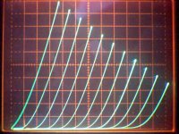
Then there's the perfect triode, an old low gm pentode wired in triode mode:
http://www.diyaudio.com/forums/tubes-valves/170746-could-perfectly-linear-triode-10.html#post2257342
That 6SN7 looks like it gets beat by any old pentode.
If you want to see great triodes, they are high current rated (big flat cathode) sweep tubes wired in triode mode.
http://www.diyaudio.com/forums/tubes-valves/170746-could-perfectly-linear-triode-10.html#post2257342
That 6SN7 looks like it gets beat by any old pentode.
If you want to see great triodes, they are high current rated (big flat cathode) sweep tubes wired in triode mode.
Attachments
Last edited:
Yes, you basically want a valve with cathode, grid and anode (or g2) all the same shape (e.g. cylindrical or flat), and lowish mu so that g1 is not too near the cathode. This is why some old triodes are good: low mu, all elements cylindrical. Its nothing to do with their size (as some people think) but everything to do with their self-similar geometry.
Agree. The reason I think the big flat cathode comes out favorably is that more of the structure is coplanar (cathode, grid, plate or g2) with less end effect from the cathode edge and grid supports. And some tubes just have more careful design to get all the geometry effects co-tracking (D3a). I doubt the sweep tubes were intentionally designed to be linear, I think it's just that the physics for getting high cathode current inadvertantly favors linearity.
That crazy 1E7G breaks some of the rules though. Filamentary cathodes must act like planar sources somehow I guess. It does have planar grids and plate geometry otherwise.
That crazy 1E7G breaks some of the rules though. Filamentary cathodes must act like planar sources somehow I guess. It does have planar grids and plate geometry otherwise.
Last edited:
Just as a set of grid wires form an approximation to an equipotential plane, I guess a set of filament wires can do the same (although spacing will be much bigger). Maybe the space charge around each filament strand effectively increases its radius so the gaps become smaller.
Some valves don't do what we expect. The 6J6 is basically two planar triodes back to back, so it ought to be linear but it isn't.
Some valves don't do what we expect. The 6J6 is basically two planar triodes back to back, so it ought to be linear but it isn't.
- Status
- Not open for further replies.
- Home
- Amplifiers
- Tubes / Valves
- Triode plate resistance == internal negative feedback?