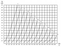
GM-70
Try this one:
Unfortunately characteristics are only for negative grid voltages.
Try this one:
An externally hosted image should be here but it was not working when we last tested it.
Thank you all for your interest in the development of the simulator.
jazbo8 -> thank you for the tube data 🙂.
Charm -> thank you too 🙂. Are attached characteristics apply to individual tube, or they are the results for averaging a set of tubes?
jazbo8 -> thank you for the tube data 🙂.
Charm -> thank you too 🙂. Are attached characteristics apply to individual tube, or they are the results for averaging a set of tubes?
Last edited:
You are welcome. The one provided by Charm looks the same as the one shown the datasheet posted by rotaspec above.jazbo8 -> thank you for the tube data 🙂.
Yesterday I had the opportunity to repair the unit with the 6111 subminiature double triode. It is so interesting that I've added it to the simulator. I hope that it may be useful to someone.
How about the 6e5p, and 12b4a?
Thanks
Yes, 6E5P would be nice, as well as 4P1L and
6S19P - small brother of 6S33S.
Yes, 6E5P would be nice, as well as 4P1L and
6S19P - small brother of 6S33S.
I'll third that proposal. 4P1L and 6e5P in triode should be really good.
Very nice app, thank you gsmok for making this available. I have been playing around with it for several weeks, and have learned that with some tubes and operating points, null points can be found for 3rd harmonic distortion. I have a reasonable understanding of the mechanism for 2nd harmonic, but can anyone shed some light on the generation (or lack of) 3rd? Also, if you're still taking requests, I have two: 12ay7, and trioded EF184. Thank you!
I'm constantly working on improving or even changing the algorithm to calculate the non-linear distortions. The present method is based on the graphic operations based on the family of anode characteristics. In this method zero values of harmonics are allowed and are connected with the errors of mathematical model of the given tube. I explained this in one of the preceding posts.
I added your tubes to the list.
I added your tubes to the list.
Last edited:
I just tried it with an ECC83. It will not let me set supply volts to less than about 267 volts.
In fact, trying it with ECC83 and ECC88 the value of Ua remains fixed all the time. Have I missed something??
Cheers
Ian
In fact, trying it with ECC83 and ECC88 the value of Ua remains fixed all the time. Have I missed something??
Cheers
Ian
Last edited:
Interesting, if you limit Ua to 100V (using the new commands at the bottom) you can display with bigger resolution ; with ECC88 you can get 10V out at 0,15% THD (mostly h3)
45V on the plate @ 2.5mA, -1.2V grid (Ra 22K, Rk 470)
45V on the plate @ 2.5mA, -1.2V grid (Ra 22K, Rk 470)
I just tried it with an ECC83. It will not let me set supply volts to less than about 267 volts.
In fact, trying it with ECC83 and ECC88 the value of Ua remains fixed all the time. Have I missed something??
Cheers
Ian
I am not sure I understand the problem. The minimum allowable anode voltage depends on the selected operating point (on the white curve) and the amplitude of the input voltage (yellow curves). For example try to minimize the input voltage and you will have the wider range of anode voltage to your usage. Simulator automatically limits the ranges of voltages and currents to fulfill the requirements of the real circuit.
Interesting, if you limit Ua to 100V (using the new commands at the bottom) you can display with bigger resolution ; with ECC88 you can get 10V out at 0,15% THD (mostly h3)
45V on the plate @ 2.5mA, -1.2V grid (Ra 22K, Rk 470)
During the simulation for very small anode voltages must be taken into account that the Koren's model accuracy decreases with anode voltage.
So I think that it is possible that a good idea would be to determine the second model parameters for the smaller anode voltages independently and do simulations on two models of a given tube without changing ranges (resolution).
Last edited:
I am not sure I understand the problem. The minimum allowable anode voltage depends on the selected operating point (on the white curve) and the amplitude of the input voltage (yellow curves). For example try to minimize the input voltage and you will have the wider range of anode voltage to your usage. Simulator automatically limits the ranges of voltages and currents to fulfill the requirements of the real circuit.
Ah, I see. Perhaps it would help if the page included short instructions on how to use it??
Cheers
Ian
Ah, I see. Perhaps it would help if the page included short instructions on how to use it??
Cheers
Ian
You're absolutely right. For a long time I try to do the manual 😱
You're absolutely right. For a long time I try to do the manual 😱
It would take only 30 minutes to write some basic instructions. I think the investment would be well worth while to popularise this excellent tool.
Cheers
Ian
- Home
- Amplifiers
- Tubes / Valves
- Triode/Pentode Loadline Calculator
