Hi all,
Have not read all the post yet, so if anything double, sorry in advance.
I have build several prototypes and gained insights. Developed even a theory about how it works, and it seems i am on the money because using the theory, i was able to gain some dB's.
I can confirm that it works, very well actually. My prototypes had it's flaws, but after listening to it for a while, normal speakers sound bloated and very slug-is.
About the rotor-diagram. Solid is better for several reasons. Because the main thing here is that the rotor itself must not create sounds by itself. This is different from most other loudspeaker designs. Even skin vibrations (NXT principle) are not wanted, because it diffuses the sound. Also, in a hollow rotor-diagram, it act's like a pipe that amplifies the surface vibration. And a thin wall of the rotor makes that it can more easily twisted (NL=torteerd) and also create surface vibration. following my theory, it is all about turbulence created at the sharp edges and the side surfaces by the edge. More turbulence, more sound.
About the bearings; I tried a step motor als a bearing and the motor, does work, but the angle of the step motor is way to small to get a good rotation. You could however use a digital music sample, compare it with the previous sample, and let a CPU calculate how much rotation is needed and feed that to the step motor. No homing magnet is needed then and you can spin faster to create more sound.
An other option is to create a bearing like Altmann used for it's record player. Maybe some of that cool Harley Davidson attitude robs of on the speaker 🙂 read more over herehttp://www.altmann.haan.de/turntable/
Last quick remark; The rotor only creates a negative sound wave. No positive. So no cancelation, but lower spl levels. So in theory (have to work that out though) the rotor can not work together with a "normal" dynamic driver because the peak SPL's are offset.
Planot theory
See also this thread: http://www.diyaudio.com/forums/showthread.php?s=&threadid=121046
First some experiment John suggested, but didn't clearify much for me:
....
It is the rotation that produces the sound. There is no other movement of the diaphragm other than the rotation. I believe I have failed in communicating this fact. Many people including engineers have assumed as you have that the rotation is separate from
but related to sound production. The use of a rotating diaphragm has been used by NASA and by two loudspeaker companies. My discovery of this mode was documented by
me approximately 30 years ago and predates all previous records and implementations.
Jelle: Could not find the mentioned documents 🙁
The mass in the Planot speaker influences the performance differently than it would with a diaphragm with pistonic movement. The forces are different. In a piston the mass of the whole unit contributes equally. When a mass rotates then the part of the mass that
contributes the most to performance is farthest from the center of rotation. With a triangular cross section most of the mass is close to the center of rotation.
I can say with scientific certainty that I do not know why it works! Having said that it does work. I have an idea why it works.
Jelle: my theory is included at the bottom
It is a special case that is not considered by the present art. Try this experiment.
Cut out an equilateral triangle out of cardboard. take a "push-pin" and pierce the exact center of the triangle. I would suggest using a triangle whose sides are two inches long--the size does not matter but a larger shape is easier to manipulate. Get a piece of
graph paper with small cells (1/4" to 1/8") and uses rubber cement to glue the graph paper to a piece of foam core. Pin the triangle to the center of the graph paper at the intersection of four cells. Place this assemble on a flat smooth surface. Sprinkle fine grained salt over the triangle. Brush the top of the triangle free of salt so that the "edge" of the triangle only is covered with salt. Carefully rotate the triangle. You will see that the salt is moved such that most of the salt is moved (positive sound pressure) and very little left unmoved (negative sound pressure).
Brush all of the salt off of the assembly and now look at the edge of the triangle as it passes each cell. There is an optical illusion operative here. If you look closely and without prejudice you will see the forward moving face moving forward and the "backside" of the face actually moving forward but on a different vector.
It is my belief that when tested or modeled on a supercomputer, which is a goal of mine, that this fact will be born out. Since there is little or no negative pressure generated there is no phase cancelation!
Jelle: I rather think it only creates negative pressure waves en no positive
......
An octagonal cross section is even better but it has a shallower angle of attack towards the air. The octagonal cross section is probably best suited for a bass only speaker or a subwoofer but further research needs to be done in this area but this implementation
is covered in my patent application.
Here is my theory:
First i thought it was slingshoting the air away, but then there has to be a positive pressure wave on the front followed by a negative pressure wave at the back of the sharp edges. So i quickly rejected that idea. I once read about a programmer (believe it was Steve Wozniak) who was totally intrigued about why planes could fly. The normal explanation about speeding air on the long side of the wing didn't cut it for him. If so, why could a paper plane fly with flat wings. I would like to add also that during stunt flying, when the plane is upside down, following the learned theory, the "lift" force would is reversed and in doing so, would push the airplane to the ground. Which it doesn't. Also, why would air speed up? what force is applied to accelerate the air?
So out with the old theory and in with the new.
This is what i came up with:
Air striking over the top part of the wing follows it contours. Why, because air, like everything else in nature wants to keep moving forward unless a force is applied to change it direction. Because of the wing surface, the air has to move upward following the wing profile. On the highest point, the air can retake again a straight line, because there is nothing left to force it in a other direction. And now the beauty of it all reveals itself. (Fig 1) Between the surface of the wing and the air moving in a straight line from the highest point of the wing, there is air trapped. The moving air creates a venturi force on the trapped air, creating heavy turbulence (vortexes). Now my statement: Turbulence air has a lower density then still air, thus creating a negative pressure (for example; twister). This negative pressure sucks the plane wing upward. To explain upside down flying and paper airplanes: there is an angle between the wing and the air flow (fig 3). Thus creating that needed surface bound turbulence.
here is a picture of it:
In Fig 2 there is the diagram cross section of the planot speaker like John uses. The speed of the rotation creates different size of vortexes. Small rotation, small vortex, small negative pressure, air sucked toward rotor in small quantities, Small sound. faster/bigger angle rotation, bigger (stretched) vortex, bigger neg. pressure, more air sucked toward the rotor, bigger sound. Because the music fluctuates, the "sucking of air" is for a little while, so the air piles up around the rotor (higher pressure then in the rest of the room). When the rotor stops (to go back again) the collected air flows back towards the room again. Try to visualize this. Rotor on; air flows towards rotor rotor off: air flows away from the rotor. Repeat quickly, and we have excited air particles just like a dynamic piston speaker would do. Let's call this delta P(ressure).
Following this theory i made this three different diagram rotors:
Result: more lows
result: more highs
result: NO SOUND!!! the angle seems to be to high to create that needed surface bound vortexes/turbelance
So in conclusion; we need to figure out how to create the biggest/strongest surface bound vortexes (S.B.V.) with a rotor that is fast enough to change direction 18,000 times a second. Higher would be nice though, but i am personally not sure it would pay off in this design. My feeling about supertweeters in conventional speakers was that the air movement helps control the 10-20khz range of sound waves. But this thing is so pure, that i doubt that it needs "help"
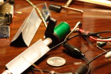
Picture below is one of my first prototypes without homing magnet.
Setup was iMac (itunes with test tones and sweeps, eq off) -> simple few watt amp salvaged from a old computer speaker system (altec lansing) -> HDD head engine. Playing 10khz-17khz tones are clearly audible, higher not anymore. Not sure it was the amp failing, or my ears, or just that it didn't output anymore.
Sound: the bearing allowed for to much forward/backward motion. That had a negative impact on sound and spl's in the low/mid region. Using frequency sweep there where 4 big resonance peaks audible. Disassembled the prototype, tested with only the HDD. same result. So it was the engine that gave that uneven spl output.
What my prototype did learn me so far is that due to it's construction it could handle much greater power to make bigger air "moves". Also that you have to be careful about generating surface vibrations, which creates sound like the NXT speaker technology. The last has a very negative influence in the sound (cancellation). Because when the above
applies. The biggest delta p happens when the triangle is moving fastest (Greatest angular acceleration) and not when it's standing still at each end of the rotation. But other speakers have the highest delta P at it's outward position. So you could talk of a kind of phase difference when Planot and pistionic speakers are compared.
The surface vibrations seems to cancel out the sound due to the phase difference. I could hear differences listening close to the diagram when the ear was held near the point (cleaner sound) or held near the flat side (NXT kinda sound). Because of restrictions in available material, i used a wooden rectangular rod instead of triangle.
See also this thread: http://www.diyaudio.com/forums/showthread.php?s=&threadid=121046
First some experiment John suggested, but didn't clearify much for me:
....
It is the rotation that produces the sound. There is no other movement of the diaphragm other than the rotation. I believe I have failed in communicating this fact. Many people including engineers have assumed as you have that the rotation is separate from
but related to sound production. The use of a rotating diaphragm has been used by NASA and by two loudspeaker companies. My discovery of this mode was documented by
me approximately 30 years ago and predates all previous records and implementations.
Jelle: Could not find the mentioned documents 🙁
The mass in the Planot speaker influences the performance differently than it would with a diaphragm with pistonic movement. The forces are different. In a piston the mass of the whole unit contributes equally. When a mass rotates then the part of the mass that
contributes the most to performance is farthest from the center of rotation. With a triangular cross section most of the mass is close to the center of rotation.
I can say with scientific certainty that I do not know why it works! Having said that it does work. I have an idea why it works.
Jelle: my theory is included at the bottom
It is a special case that is not considered by the present art. Try this experiment.
Cut out an equilateral triangle out of cardboard. take a "push-pin" and pierce the exact center of the triangle. I would suggest using a triangle whose sides are two inches long--the size does not matter but a larger shape is easier to manipulate. Get a piece of
graph paper with small cells (1/4" to 1/8") and uses rubber cement to glue the graph paper to a piece of foam core. Pin the triangle to the center of the graph paper at the intersection of four cells. Place this assemble on a flat smooth surface. Sprinkle fine grained salt over the triangle. Brush the top of the triangle free of salt so that the "edge" of the triangle only is covered with salt. Carefully rotate the triangle. You will see that the salt is moved such that most of the salt is moved (positive sound pressure) and very little left unmoved (negative sound pressure).
Brush all of the salt off of the assembly and now look at the edge of the triangle as it passes each cell. There is an optical illusion operative here. If you look closely and without prejudice you will see the forward moving face moving forward and the "backside" of the face actually moving forward but on a different vector.
It is my belief that when tested or modeled on a supercomputer, which is a goal of mine, that this fact will be born out. Since there is little or no negative pressure generated there is no phase cancelation!
Jelle: I rather think it only creates negative pressure waves en no positive
......
An octagonal cross section is even better but it has a shallower angle of attack towards the air. The octagonal cross section is probably best suited for a bass only speaker or a subwoofer but further research needs to be done in this area but this implementation
is covered in my patent application.
Here is my theory:
First i thought it was slingshoting the air away, but then there has to be a positive pressure wave on the front followed by a negative pressure wave at the back of the sharp edges. So i quickly rejected that idea. I once read about a programmer (believe it was Steve Wozniak) who was totally intrigued about why planes could fly. The normal explanation about speeding air on the long side of the wing didn't cut it for him. If so, why could a paper plane fly with flat wings. I would like to add also that during stunt flying, when the plane is upside down, following the learned theory, the "lift" force would is reversed and in doing so, would push the airplane to the ground. Which it doesn't. Also, why would air speed up? what force is applied to accelerate the air?
So out with the old theory and in with the new.
This is what i came up with:
Air striking over the top part of the wing follows it contours. Why, because air, like everything else in nature wants to keep moving forward unless a force is applied to change it direction. Because of the wing surface, the air has to move upward following the wing profile. On the highest point, the air can retake again a straight line, because there is nothing left to force it in a other direction. And now the beauty of it all reveals itself. (Fig 1) Between the surface of the wing and the air moving in a straight line from the highest point of the wing, there is air trapped. The moving air creates a venturi force on the trapped air, creating heavy turbulence (vortexes). Now my statement: Turbulence air has a lower density then still air, thus creating a negative pressure (for example; twister). This negative pressure sucks the plane wing upward. To explain upside down flying and paper airplanes: there is an angle between the wing and the air flow (fig 3). Thus creating that needed surface bound turbulence.
here is a picture of it:
An externally hosted image should be here but it was not working when we last tested it.
In Fig 2 there is the diagram cross section of the planot speaker like John uses. The speed of the rotation creates different size of vortexes. Small rotation, small vortex, small negative pressure, air sucked toward rotor in small quantities, Small sound. faster/bigger angle rotation, bigger (stretched) vortex, bigger neg. pressure, more air sucked toward the rotor, bigger sound. Because the music fluctuates, the "sucking of air" is for a little while, so the air piles up around the rotor (higher pressure then in the rest of the room). When the rotor stops (to go back again) the collected air flows back towards the room again. Try to visualize this. Rotor on; air flows towards rotor rotor off: air flows away from the rotor. Repeat quickly, and we have excited air particles just like a dynamic piston speaker would do. Let's call this delta P(ressure).
Following this theory i made this three different diagram rotors:
An externally hosted image should be here but it was not working when we last tested it.
Result: more lows
An externally hosted image should be here but it was not working when we last tested it.
result: more highs
An externally hosted image should be here but it was not working when we last tested it.
result: NO SOUND!!! the angle seems to be to high to create that needed surface bound vortexes/turbelance
So in conclusion; we need to figure out how to create the biggest/strongest surface bound vortexes (S.B.V.) with a rotor that is fast enough to change direction 18,000 times a second. Higher would be nice though, but i am personally not sure it would pay off in this design. My feeling about supertweeters in conventional speakers was that the air movement helps control the 10-20khz range of sound waves. But this thing is so pure, that i doubt that it needs "help"
Picture below is one of my first prototypes without homing magnet.
An externally hosted image should be here but it was not working when we last tested it.
Setup was iMac (itunes with test tones and sweeps, eq off) -> simple few watt amp salvaged from a old computer speaker system (altec lansing) -> HDD head engine. Playing 10khz-17khz tones are clearly audible, higher not anymore. Not sure it was the amp failing, or my ears, or just that it didn't output anymore.
Sound: the bearing allowed for to much forward/backward motion. That had a negative impact on sound and spl's in the low/mid region. Using frequency sweep there where 4 big resonance peaks audible. Disassembled the prototype, tested with only the HDD. same result. So it was the engine that gave that uneven spl output.
What my prototype did learn me so far is that due to it's construction it could handle much greater power to make bigger air "moves". Also that you have to be careful about generating surface vibrations, which creates sound like the NXT speaker technology. The last has a very negative influence in the sound (cancellation). Because when the above
applies. The biggest delta p happens when the triangle is moving fastest (Greatest angular acceleration) and not when it's standing still at each end of the rotation. But other speakers have the highest delta P at it's outward position. So you could talk of a kind of phase difference when Planot and pistionic speakers are compared.
The surface vibrations seems to cancel out the sound due to the phase difference. I could hear differences listening close to the diagram when the ear was held near the point (cleaner sound) or held near the flat side (NXT kinda sound). Because of restrictions in available material, i used a wooden rectangular rod instead of triangle.
Below the first magnetic bearing (thanks for knetix toys):
Second bearing, works surprisingly well. Just needed a quick to assemble bearing to test X-diagram. Use wood pin (mine's was normally used to stick meat together nl=sateprikker) and drilled a hole, just a fraction bigger then the pin in the rotor. Maybe fill it with oil or graphite powder to even get tighter tolerances...
My current test engine with the homing magnet:
2 Neo magnets in wood; iron bearing pressed between alu arms of HDD head.
About the homing magnet, which i don't like because it can create resonance (acts like a spring) and burns of power for rotation. But the sound becomes stronger and deeper with it. Because my engine does not center without current (lead wires), on the cross overpoint of the electric signal, there is no controlling force off the engine and the rotor can wobble freely. So the homing magnet keeps the rotor still during this crossover point. It's like crossover distortion in cables and electronics.
http://en.wikipedia.org/wiki/Crossover_distortion. A.J. vd Hul from vd Hul audio cables talked a lot about this distortion and that we humans are very sensitive to it.
For my next prototype:
-bigger and longer rotor
-magnets inside rotor, 2 voice coils alongside it, parellel, one in reverse [N-S] <rotor> [N-S]
-homing magnet in front and between the 2 voicecoils
Future, Direct drive amp to each individual coil to lose that homing magnet.
An externally hosted image should be here but it was not working when we last tested it.
An externally hosted image should be here but it was not working when we last tested it.
Second bearing, works surprisingly well. Just needed a quick to assemble bearing to test X-diagram. Use wood pin (mine's was normally used to stick meat together nl=sateprikker) and drilled a hole, just a fraction bigger then the pin in the rotor. Maybe fill it with oil or graphite powder to even get tighter tolerances...
An externally hosted image should be here but it was not working when we last tested it.
My current test engine with the homing magnet:
An externally hosted image should be here but it was not working when we last tested it.
2 Neo magnets in wood; iron bearing pressed between alu arms of HDD head.
About the homing magnet, which i don't like because it can create resonance (acts like a spring) and burns of power for rotation. But the sound becomes stronger and deeper with it. Because my engine does not center without current (lead wires), on the cross overpoint of the electric signal, there is no controlling force off the engine and the rotor can wobble freely. So the homing magnet keeps the rotor still during this crossover point. It's like crossover distortion in cables and electronics.
http://en.wikipedia.org/wiki/Crossover_distortion. A.J. vd Hul from vd Hul audio cables talked a lot about this distortion and that we humans are very sensitive to it.
For my next prototype:
-bigger and longer rotor
-magnets inside rotor, 2 voice coils alongside it, parellel, one in reverse [N-S] <rotor> [N-S]
-homing magnet in front and between the 2 voicecoils
Future, Direct drive amp to each individual coil to lose that homing magnet.
sateprikker = "skewer." But you're making me hungry for sate.😀
Seriously, a very nice piece of work, very well documented. Thanks!
Seriously, a very nice piece of work, very well documented. Thanks!
slightly OT
Sounds like an Urban Legend. Anyone who has read the classic basic book about airplanes ("Stick and Rudder," Langewiesche, 1944) knows how a wing works.
The normal explanation about speeding air on the long side of the wing didn't cut it for him.
Sounds like an Urban Legend. Anyone who has read the classic basic book about airplanes ("Stick and Rudder," Langewiesche, 1944) knows how a wing works.
Re: slightly OT
Thanks for the tip and nice words!
The book can be found here: http://books.google.com/books?id=zlaqYZYJZwQC&dq=Stick+and+Rudder+Langewiesche&printsec=frontcover&source=bn&hl=nl&sa=X&oi=book_result&resnum=4&ct=result#PPA29,M1
SY said:Sounds like an Urban Legend. Anyone who has read the classic basic book about airplanes ("Stick and Rudder," Langewiesche, 1944) knows how a wing works.
Thanks for the tip and nice words!
The book can be found here: http://books.google.com/books?id=zlaqYZYJZwQC&dq=Stick+and+Rudder+Langewiesche&printsec=frontcover&source=bn&hl=nl&sa=X&oi=book_result&resnum=4&ct=result#PPA29,M1
Thanks, putting in links that works a little different than i am used too.
All ready started building a new prototype. Gone try the push/pull with normal speaker spider first. But at first sight, the rotation angle is gone be quite low.
Here some pictures:
Speaker donor
Removed cone and added a crossbar; gone add a rod to it later that connects to the diagram later:
Frame: Old Ikea CD holder.
Added the diagram rotor; only have to figure out how to attach the driver somewhere in the middle.
Close up of the cheapest bearing made of 5,5 cm skewer and filed with oil. Runs quit well. Only have to replace the bottom one because it's splintert when it was cut. Result is that there is a scrapping noise if it starts to turn. Also this solution would not be the longest lasting option out there. If i have to money, i would like to try the altmann bearing, which is gone cost me about €113 ($158).
Was looking at stepper motors. There seems to be only a few flavors: 1.8/7.5/15 degree. On the low side to my tasting.
But what about RC servomotors from remote controlled cars and such? Has a reasonable angle. Only have to look into how there driven.
Edit: RC servo is not an option. There driven linear to the desired position. We need proportional drive 🙁 But maybe use a high angle step motor, attach a big round disc to it. Mount small disc to rotor and connect the 2 with a rubber band. Sort of like a reversed pickup set-up. This way the small angle (15 degree's) are "amplified to a much bigger angle". I wonder what will happen if we could succeed to get a couple of turns of the diagram rotor. High SPL is what i reckon.
All ready started building a new prototype. Gone try the push/pull with normal speaker spider first. But at first sight, the rotation angle is gone be quite low.
Here some pictures:
Speaker donor
An externally hosted image should be here but it was not working when we last tested it.
Removed cone and added a crossbar; gone add a rod to it later that connects to the diagram later:
An externally hosted image should be here but it was not working when we last tested it.
Frame: Old Ikea CD holder.
An externally hosted image should be here but it was not working when we last tested it.
Added the diagram rotor; only have to figure out how to attach the driver somewhere in the middle.
An externally hosted image should be here but it was not working when we last tested it.
Close up of the cheapest bearing made of 5,5 cm skewer and filed with oil. Runs quit well. Only have to replace the bottom one because it's splintert when it was cut. Result is that there is a scrapping noise if it starts to turn. Also this solution would not be the longest lasting option out there. If i have to money, i would like to try the altmann bearing, which is gone cost me about €113 ($158).
An externally hosted image should be here but it was not working when we last tested it.
Was looking at stepper motors. There seems to be only a few flavors: 1.8/7.5/15 degree. On the low side to my tasting.
But what about RC servomotors from remote controlled cars and such? Has a reasonable angle. Only have to look into how there driven.
Edit: RC servo is not an option. There driven linear to the desired position. We need proportional drive 🙁 But maybe use a high angle step motor, attach a big round disc to it. Mount small disc to rotor and connect the 2 with a rubber band. Sort of like a reversed pickup set-up. This way the small angle (15 degree's) are "amplified to a much bigger angle". I wonder what will happen if we could succeed to get a couple of turns of the diagram rotor. High SPL is what i reckon.
Servomotors from radio controlled vehicles are too slow. They have a very high ratio gearbox attached to a small DC or coreless motor inside. I would think a 1.8 degree stepper would be best, as you seem to have a lot of rotational inertia in that armature (diaphragm) to move. There was a commercially offered subwoofer that used a stepping or servo motor driving a twin bladed rotor a few years back.
This driver is an interesting design, but I think you will find the rotational inertia of the assembly, coupled with the natural limitations regarding the torsional rigidity of your armature will make the working physical embodiment "difficult". At the very least, you will have a very complex series of torsional resonances that propagate along the length of the stator, creating strong destructive vibrational nodes.
This driver is an interesting design, but I think you will find the rotational inertia of the assembly, coupled with the natural limitations regarding the torsional rigidity of your armature will make the working physical embodiment "difficult". At the very least, you will have a very complex series of torsional resonances that propagate along the length of the stator, creating strong destructive vibrational nodes.
Just did 2 test:
1) using the normal speaker to drive the rotor; no-go. To little movement. The speaker itself produces more sound then the rotor. Also, the sound made resembled more NXT kinda sound. So more survice vibration instead of rotation motion.
2) embedded 26 small (round, 8mm across/4mm high) Neo magnets in the rotor. Got a coil of a HDD head and wired that to an amp: Held the coil near the magnets. No movement. Gaps are to great and/or created forces to small. Only very faint sounds and you can feel the coil vibrate in your hand.
Sigh.... Back to the drawing board....
Jelle, some of us have had a shot at this.
The problem is the need for precise engineering and high tolerances to MAKE the rotor or motor.
The planot home page shows the relative simplicity of the motor, but it's the quality that counts . This is what makes it work. How well we still don't know and the company is very slow in producing any evidence that it does sufficiently for audio/high fidelity purposes.
I personally am very suspicious of this concept. But who knows.....ONE DAY (!!!!) WE'LL FIND OUT ??????????
Just found something nice:
Air coil engine with claimed 98% efficiency:
http://www.sternen-motoren.de
But seems to be an other disregarded genius without production facilities.
Air coil engine with claimed 98% efficiency:
http://www.sternen-motoren.de
But seems to be an other disregarded genius without production facilities.
Well, this guy seems to have a faible for esotherics, but I like his motor concept. The question I see is: How complicated is winding these strange coils, and does it need new machinery? And if so: Are there enough applications that need the higher efficiency to justify the investments?
Some people are just strange...but ideas do not make it.
It needs plain numbers, one conventional motor against a 'new' one...
Motors usually have good efficiency, so beat them! 😉
Regards
It needs plain numbers, one conventional motor against a 'new' one...
Motors usually have good efficiency, so beat them! 😉
Regards
BLDC motors anyone?
The mention of magnet motors gave me the idea of using brushless motors for a planot-like prototype. I'll be the first to say that my attempt is nothing like planot and the poor results are my own doing. Just wanted to share in the hopes of inspiring someone else.
Being into mini RC, I had an old Mamba motor to try this out. The motor is a three phase motor. As such there are three sets of coils, only two sets were used.
In the attached pic the motor (green can) is attached to a motor mount. The shaft is attached to a pinion gear which is attached to plastic pen tube, over the tube is the triangle formed from a soda can. For testing the motor mount was vise-griped to table. Used an old JVC 100 watt receiver to power it. Volume passed half-way would trip the JVC. Not unexpected since it is a motor and impedance is badly mismatched. The motor is also busted, that is some of the windings are shorted, had to continually re-orient the shaft to get better sound.
The BAD:
Efficiency was to say dismal compared to conventional speaker. Hardly any sound when listening even 1 inch away. Sound was mostly midrange and badly equalized at that. The low end can only be heard and felt from the table, nothing from the triangle. To ease removal and testing, the triangle was not glued on. This contributed to the poor performance.
The Good:
Using larger size triangles did improve volume. On low to moderate volume, the triangle kept orientation for the most part, thus a "surround/spider" magnet set was not used. Pressing the pen tube (triangle removed) against the backside of my ear, produced much better sound, the response favored the lowend but mid and highs were present. Stanglely enough biting down on the pen tube was also audible, very weird sensation hearing music through your mouth! I could sense (both tactile methods ear/mouth) 15hz-13khz with a sharp drop at the high end.
Thoughts:
Sound from BLDC motors is possible at least in a tactile way. Stereo Tactile headphones using BLDC is certainly doable, hmmm wonder if a there is a patent in that idea.
Yes, ideally I should have used two motors one at each end, but I had only one.
Need to scale up. The motor and triangle used are small, both are about 20mm across.
The planot speaker seems to be using an air core(ironless coil), which could be an important factor that both conventional speakers and BLDC motors cannot match.
More on BLDC:
http://www.allegromicro.com/en/Products/Design/compumot/a17a19.pdf
Attachments
redninja, the PLANOT's motor is a high quality version of a hard drive positioning arm motor - that's all.
What makes it work is the high tolerances used to manufacture it.
There are many forces at work when it produces sound (whatever that is) - distributed modes (which you have discovered) is the first and primary one. These unwanted vibrational sound sources is what the designer has gone to great lengths to avoid looking at his home page picture (or has he? ).
).
A couple of us have duplicated rough versions of this system and have found that vibrations travelling from the voice coil motor, through the mounting and anything it touches is where most of the sound is coming from. Yes there was some sound from the triangular diaphragm, but it was not the primary source. Vibrating mounts , desk tops, floors were all in on the action.
But, don't let this deter you, keep up the experiments and let us know how you go😉
What makes it work is the high tolerances used to manufacture it.
There are many forces at work when it produces sound (whatever that is) - distributed modes (which you have discovered) is the first and primary one. These unwanted vibrational sound sources is what the designer has gone to great lengths to avoid looking at his home page picture (or has he?
).A couple of us have duplicated rough versions of this system and have found that vibrations travelling from the voice coil motor, through the mounting and anything it touches is where most of the sound is coming from. Yes there was some sound from the triangular diaphragm, but it was not the primary source. Vibrating mounts , desk tops, floors were all in on the action.
But, don't let this deter you, keep up the experiments and let us know how you go😉
Ziggy said:redninja, the PLANOT's motor is a high quality version of a hard drive positioning arm motor - that's all.
vibrations travelling from the voice coil motor, through the mounting and anything it touches is where most of the sound is coming from. Yes there was some sound from the triangular diaphragm, but it was not the primary source. Vibrating mounts , desk tops, floors were all in on the action.
But, don't let this deter you, keep up the experiments and let us know how you go😉
When I look at hard drive "speakers" I noticed that the actuator and head are so small that I doubt they'd move 1/10th the air of a tweeter. They seem to be getting most of their volume by vibrating the metal platters.
What would happen if you replaced the metal platter (from a hard drive "speaker") with a thin hard piece of wood or plastic?
Maybe this works in the same way a horn speaker works?
This is exactly what we did, only the balsa wood triangle/rod was attached directly to the hard drive arm centre where the energy is at it's greatest.
You'll be surprised how much movement and force is present at this point of the hard drive.
The main sound comes from vibrations from the hard drive casing caused by the coupling of the arm to it.
No, that's not how a horn works.
You'll be surprised how much movement and force is present at this point of the hard drive.
The main sound comes from vibrations from the hard drive casing caused by the coupling of the arm to it.
No, that's not how a horn works.
- Status
- Not open for further replies.
- Home
- Loudspeakers
- Planars & Exotics
- Triangle shaped metal music maker?