Oops! Thanks for catching the Rg; in my haste I just copied/changed the title of an existing sim, though in retrospect it might be a good idea to compare a matching impedance [Rg = 4 ohms] version also.
GM
GM
Oops! Thanks for catching the Rg; in my haste I just copied/changed the title of an existing sim,
There's nothing wrong with having .1 ohm Rg in the sim, it's usually a pretty good idea to do so in most cases. The only reason I took it out was because I was worried I'd forget to do all the sims exactly the same. Rg is easy to forget about. There's no Rg at all in any of the sims I posted (except in the first Akabak sim which was corrected in the next post).
... though in retrospect it might be a good idea to compare a matching impedance [Rg = 4 ohms] version also.
GM
Not sure what you mean here. Rg = 4 ohms is a LOT of added series resistance. That would more than double Re in this sim.
But if you want to see something else compared, just throw in another Hornresp export and I'll do it when time permits. I'd prefer to do dramatically different alignments for comparison though, not something almost exactly the same.
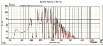
Since no one else seems interested in commenting on the comparison I just did I'll comment on it myself.
It looks like the TL.app results compare very favorable with all the other programs. Accuracy does not appear to be an issue here.
I'm still going to do a couple of other comparisons, maybe a complex front loaded horn and a simple tl with a branch but I'm not sure when I'll have time to do them. And based on the results of the first comparison I'm expecting similar (accurate) results.
I'm not going to bother doing a tapped horn comparison until the tapped horn feature is fixed.
Maybe we should lobby to get this thread put back into the subwoofer section where it started. It isn't getting much exposure in the software section. It's grossly unfair that the Hornresp thread gets to stay in the subwoofer section but this thread can't. I complained when it got moved, but ironically I don't think any moderators saw my complaint because it got moved to this obscure location.
Thanks for doing those comparisons J-a-G.
I'm glad there aren't many differences, I'll look into it in a bit more detail next year. I have made a slight improvement to the radiation impedance model but the effect is very small.
Differences will likely come up with more complex designs but its always good to know that the starting point (I.e. a simple TL) is modelling in an accurate way.
Regarding moving the thread. I would prefer it to be in subwoofers and I have mentioned to the mods but they don't seem to be wanting to move it. Maybe I'll ask again soon.
Cheers and Merry Christmas,
Pete
Hi Smeet,
Just updated to the latest version after a while (been busy with other non audio projects, RF / Antenna design is also a lot of fun 😉 )
I noticed you added a filter window, very nice, but - if I may - can I suggest some additional filters (been on my wish list since I've been using the program 😛 )
- Shelfing filters
- Linkwitz transform (I use it in an EQSS type design, would really like to try it with a TL)
- First order
- PEQ
Maybe make 10 blocks that you can select the type and parameters of and enable / disable the blocks so you can simulate a complete design (minus the baffle step / diffraction).
Anyway, keep up the good work, this is the first TL program that is easy to use and accurate as far as I know, very impressive!
Great stuff!
I looked at one of the very early versions when your software was first released, and all I can say is wow! You have done a ton of work on this. I really like the approach and what you are trying to accomplish with it. I personally like that it isn't Java, but that is just one man's opinion.
I am going to spend some time with it this week and then get you some feedback.
Very nice.
@ schmeet
Hi, could you include a box in the driver specs panel so we can input vendors SPL @ 1W. This makes it quicker to decide whether or not to begin considering one for a particular design in the first place 😉
Thanx for your continued work on this 🙂
Hi, could you include a box in the driver specs panel so we can input vendors SPL @ 1W. This makes it quicker to decide whether or not to begin considering one for a particular design in the first place 😉
Thanx for your continued work on this 🙂
@ schmeet
Hi, could you include a box in the driver specs panel so we can input vendors SPL @ 1W. This makes it quicker to decide whether or not to begin considering one for a particular design in the first place 😉
Thanx for your continued work on this 🙂
Just so that it is stored and that you can see it?
Sure...
Originally Posted by schmeet
Just so that it is stored and that you can see it?
Yes Thanx 🙂
I don't care either way if this feature is included, but this can be very misleading. Sometimes it isn't specified at 1w at all, it's common to be shown at 2.83V regardless of impedance. And it's usually specified for the midband (and sometimes at a midband peak), not at frequencies that we use for sub design. So I doubt this would be useful for what you want to use it for, it might actually cause problems.
Thats quite a good point Just-a-Guy. I'll have a think about this, maybe it's not such a good thing to include.
@ just a guy
It's only so it's stored and that we can see it, for comparison against other drivers. Not for simulation purposes 😉
It's only so it's stored and that we can see it, for comparison against other drivers. Not for simulation purposes 😉
I don't really see the need for it. It is a calculated level and not a measured value.
Peter, will have more info for you shortly. 😉
Peter, will have more info for you shortly. 😉
@ just a guy
It's only so it's stored and that we can see it, for comparison against other drivers. Not for simulation purposes 😉
I understand that, and if you want to compare what different drivers are like at 1khz it's a great way to do it.
But like I said, midband efficiency is of no concern to subwoofer designers, and it's commonly listed in a way that you can't compare different drivers anyway. (2.83V regardless of impedance).
Maybe try a little experiment. Use a pro driver with a very high published 1w spl and a home market sub driver with a very low 1w spl. Put them both in a 4th order bandpass box tuned to 20 hz. I think you will find that the published 1w spl has no meaning whatsoever at subwoofer frequencies and trying to use it for that purpose will just cause you problems. At these frequencies the enclosure is everything, the driver is just an air pump.
I don't really see the need for it. It is a calculated level and not a measured value.
Sometimes it is measured. Sometimes it's measured at a peak in the midband. Some manufacturers will do anything they can to give inflated numbers for this spec, and for xmax and power handling.
But measured or not it's not particularly useful for subwoofer design.
That's why it's so hard to splice nearfield and far field together. LATL certainly does not account for baffle step or room modal loading.
It's an air pump at these frequencies is so true, hence the phrase "there's no replacement for displacement" 😉
It's an air pump at these frequencies is so true, hence the phrase "there's no replacement for displacement" 😉
- Home
- Design & Build
- Software Tools
- Transmission Line Modelling Software