With flow you can check for "strange" airflows in the system... I think it's a great tool for optimizing airflow in the box and get rid of all kind of vortices (noise?)...using "flow" instead of Acoustic Modeling? - not the same domain at all
Unfortunately it's too expensive for hobby use 🙁
Last edited:
No not the same domain at all. Flow in only one direction and believe this is causing confusion (high hopes). This is DC flow of only one polarity eg not acoustical.
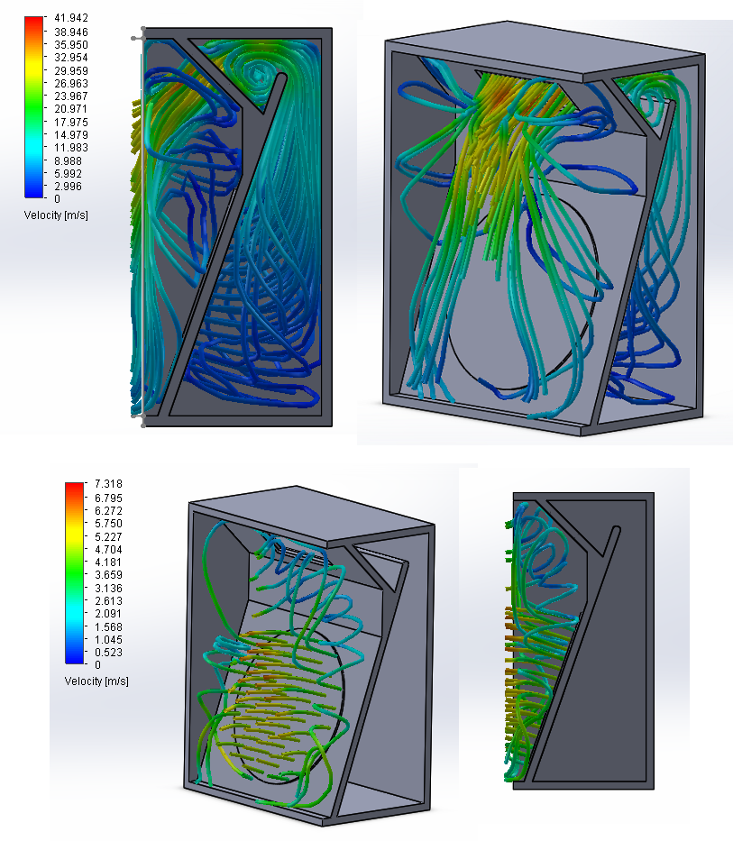
that's really something to see the Karlson type modeled - thank you very much - how would you interpret what its doing? fwiw I've seen them make a vortex in the front chamber when smoked is introduced - there's low pressure at the bottom of the front coupler and high at the top - I assume the wings are included in this sim (?) can it tell something about the cone damping when pulsed like on a drum beat?
Last edited:
Physical air flow (as in an air-conditioning duct) is not the same as sound vibrations propagating along an acoustic transmission line - where the net air flow is zero. To produce an air flow, you would need to replace the loudspeaker driver with a fan 🙂.
Last edited:
Perhaps he should lookup Bruce Thigpen 😉Physical air flow (as in an air-conditioning duct) is not the same as sound vibrations propagating along an acoustic transmission line - where the net air flow is zero. To produce an air flow, you would need to replace the loudspeaker driver with a fan 🙂.
But when you look at a speaker, the cone moves and pushes air. And when a sine wave is played you have a constant movement of the cone, right?
So my theory was that if you look at a one-way movement of the cone (so a few milliseconds of movement) you have a constant stream of air.
And this simulation shows how this air 'flows' in the inside of the box
Cone area (cm2) * Displacement (cm) = Volume of air pushed (cm3) (or ft or inches for the non-metric system users 😛)
But David, you think it can't be used for showing this?With flow you can check for "strange" airflows in the system... I think it's a great tool for optimizing airflow in the box and get rid of all kind of vortices (noise?)...
Yes, the wings are included like on the other image from that post. But they are hidden for a better view. I can't answer your other question..that's really something to see the Karlson type modeled - thank you very much - how would you interpret what its doing? fwiw I've seen them make a vortex in the front chamber when smoked is introduced - there's low pressure at the bottom of the front coupler and high at the top - I assume the wings are included in this sim (?) can it tell something about the cone damping when pulsed like on a drum beat?
Hi Michelp89,
The pictures of the Karlson are quite interesting. Are you reversing the direction of the flow when looking at the front versus the back?
Would you be able to do another set of simulations for the Keystone TH by Art (weltersys)? I have a drawing here: http://www.diyaudio.com/forums/subwoofers/185588-keystone-sub-using-18-15-12-inch-speakers-10.html in Posts #94/97. The important element is the shape and location of the opening, the Keystone. The simulations in Hornresp and AkAbak have not quite looked the same as the measured results. Maybe looking at the flow will shed some light on this.
Thank you for your efforts.
Regards,
Acoustic wave propagation isn't flow
you don't have flow - you have fractional inch to maybe few inch air molecule motion that immediately reverses
this is very significant for the result - very limited "momentum" effects, vorticity is practically zero for acoustic wave propagation - flow effects like streamlines, don't have steady unidirectional forces persisting over long enough time to develop in acoustic waves
me not David.... Me Tarzan 😀But David, you think it can't be used for showing this?
You said someting, David said something. So I was asking David if the thing you said was right. Get it Tarzan? 😀me not David.... Me Tarzan 😀
The first image is when the woofer moves inwards, the next one is when the woofer moves outwards. I'm busy tonight and the rest of the weekend, so i think i could get it done monday eveningHi Michelp89,
The pictures of the Karlson are quite interesting. Are you reversing the direction of the flow when looking at the front versus the back?
Would you be able to do another set of simulations for the Keystone TH by Art (weltersys)? I have a drawing here: http://www.diyaudio.com/forums/subwoofers/185588-keystone-sub-using-18-15-12-inch-speakers-10.html in Posts #94/97. The important element is the shape and location of the opening, the Keystone. The simulations in Hornresp and AkAbak have not quite looked the same as the measured results. Maybe looking at the flow will shed some light on this.
Thank you for your efforts.
Regards,
So where does the air which leaves the port come from? 😛you don't have flow - you have fractional inch to maybe few inch air molecule motion that immediately reverses
this is very significant for the result - very limited "momentum" effects, vorticity is practically zero for acoustic wave propagation - flow effects like streamlines, don't have steady unidirectional forces persisting over long enough time to develop in acoustic waves
I know that the movement is not a lot. It moves just a few milliseconds. But the molecules moves by the cone has to go somewhere. So this small amount of air pushes towards the other molecules. Which goes on and on and on. At least, that was my theory, I could be wrong.
Oscillation is not continuous flow
Acoustic Impedance is not flow resistance in the time, velocity, frequency and dimension range we see in speakers, boxes
as an example in continuous flow from an orifice you would get entrained air moving over the exterior surface adding to the flow - this effect can become big in "Coanda Effect"
in loudspeaker Acoustics the amplitude of air motion is small, keeps reversing too quickly for such large flow structures to develop
Last edited:
Ok... now I understandYou said someting, David said something. So I was asking David if the thing you said was right. Get it Tarzan? 😀

...... come Cheeta...
Hi Michelp89,
Post #30: " I'm busy tonight and the rest of the weekend, so i think i could get it done monday evening"
That would be just great, and having the reverse flow directions gives another interesting view to look at, and think about.
Regards,
Post #30: " I'm busy tonight and the rest of the weekend, so i think i could get it done monday evening"
That would be just great, and having the reverse flow directions gives another interesting view to look at, and think about.
Regards,
So where does the air which leaves the port come from?
It stays withing the cab, pipe, etc., on rarefaction and pushes out in compression to create a pulse wave in the surrounding air.
Maybe this will help: Resonances of open air columns
GM
Yes, there a constant movement of the cone, which creates a positive pressure wave on the forward movement, and rarefaction (a partial vacuum) on the rearward movement, no net "stream of air".But when you look at a speaker, the cone moves and pushes air. And when a sine wave is played you have a constant movement of the cone, right?
So my theory was that if you look at a one-way movement of the cone (so a few milliseconds of movement) you have a constant stream of air.
If you hold a piece of paper in front of a subwoofer, it just moves back and forth, though below box tuning, air flow can be enough to blow it some distance.
But David, you think it can't be used for showing this?
Hi Michelp89,
The tool can certainly be used to show air stream flows in enclosures - provided of course that the air is actually flowing 🙂. Unfortunately, the tool is not really applicable to loudspeakers, for the reasons given earlier.
The following example may help to clarify things:
Consider the simple acoustic system shown in the attachment. The red line is the driver diaphragm, located half-way along a circular cross-section duct. Assuming that air cannot pass through the diaphragm (which is usually the case), there is no way that a net air flow can be generated along the duct just by vibrating the diaphragm. That is why you need a fan instead 🙂
Kind regards,
David
Attachments
this effect can become big in "Coanda Effect"
As utilised to great advantage in Formula One - the master of which is aerodynamicist Adrian Newey...
fwiw I've put a port board on a 15" woofer/3 cubic foot cabinet with 43-3/8" diameter holes - with relatively low power, the distributed hole port made wind like a fan. I've also noticed woofer offset with 2-4" diameter vents in the same box. Is there such a thing as "port rectification"?
in the 1950's distributed slit and hole vent reflex boxes appeared in numbers - perhaps in hope to better match a wider
range of drivers in that mix and match age.
here's a diy Karlson type in Germany with a mix of vents
in the 1950's distributed slit and hole vent reflex boxes appeared in numbers - perhaps in hope to better match a wider
range of drivers in that mix and match age.
here's a diy Karlson type in Germany with a mix of vents
An externally hosted image should be here but it was not working when we last tested it.
Last edited:
Very interesting. I really like the approach to simulate the speaker behavior by using some FEM-simtools. But as already mentioned you need an "sonic" / oscilating airstream. Which is far more complicated then a steady "DC" flow. Of course the speaker will cause a flow but due to the compressible behavior of air (and the geometry of the enclosure) it will have a frequency dependent characteristic.
According to your pictures I guess it is a steady state simulation which means there is no time (respectively frequency) dependent characteristic distinguishable and it shows only the settled airstream for a certain inlet velocity. (For example: You could use this to analyse ..airstream noise of a bassreflex pipe due to turbulences - see B&W Speakers) but not for your purpose).
This is a multi-physics approach so you could use "Comsol Multiphysics" (commercial) - it has a very simple example sound radiation simulation for a oscillating diaphragm (but still not as easy as it may appears). Or Elmer (freeware) or ... OpenFoam (freeware) but for this I think it is maybe too difficult - but it would generate the best results. Then you have to couple several partial differential equations (in c++) of different fields...possible but tough.
(raising the difficulty level: you could also add the box resonances to the simulation 😀 )
Keep us informed about your progress.
p.s.: sorry for redundant suggestions
Last edited:
....https://www.youtube.com/watch?v=pkraAk1YQwA a little bit different but for the simulation approach it makes no difference if it is a rotating fan or an oscillating diaphragm...
- Status
- Not open for further replies.
- Home
- Loudspeakers
- Subwoofers
- Transmission line 'flow simulation'