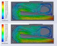
So I was bored and wanted to know the use of corner pieces in a transmission line box.
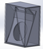
I already had a model in Solidworks so decided to do a flow simulation here.
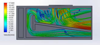
I've attached a image of what the program calculated.
One is with corner pieces, and one without.
So can I say the corner pieces are sort of useless for the airflow?
Or is there an other advantage why everyone should use them?
I already had a model in Solidworks so decided to do a flow simulation here.
I've attached a image of what the program calculated.
One is with corner pieces, and one without.
So can I say the corner pieces are sort of useless for the airflow?
Or is there an other advantage why everyone should use them?
Attachments
Hi Michelp89,
Very neat simulations.
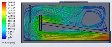
At low frequencies the corner braces only serve to stiffen the box. (They also reduce the volume.)
We have been talking about intentionally placing constrictions in ducts, wonder what that would do in the flow simulation?
http://www.diyaudio.com/forums/subw...flex-simple-build-series-tuned-6th-order.html
http://www.diyaudio.com/forums/subwoofers/175658-tham15-compact-15-tapped-horn-18.html#post2448729
Regards,
Very neat simulations.
At low frequencies the corner braces only serve to stiffen the box. (They also reduce the volume.)
We have been talking about intentionally placing constrictions in ducts, wonder what that would do in the flow simulation?
http://www.diyaudio.com/forums/subw...flex-simple-build-series-tuned-6th-order.html
http://www.diyaudio.com/forums/subwoofers/175658-tham15-compact-15-tapped-horn-18.html#post2448729
Regards,
Attachments
Hi Michelp89,
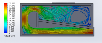
That was fast. Can you tighten the constriction to maybe half of what it is now? What would happen if there is an opening (terminus/port) @ the end where you are showing the dark blue swirl, can that be done? And what does it all mean? 🙂
Regards,
That was fast. Can you tighten the constriction to maybe half of what it is now? What would happen if there is an opening (terminus/port) @ the end where you are showing the dark blue swirl, can that be done? And what does it all mean? 🙂
Regards,
On the top is the woofer position. So that is the start point of the air movement. At the right bottom is the TL opening. So that is where al the air is going. Dark blue is low velocity, red is high velocity. Don't look at the numbers, i used random numbers at the parameters, the airflow will we about the same I think if I use a high or low volume of air.
I think I can try the stuff you say
I think I can try the stuff you say
Hi Michelp89,
There seem to be large areas that are not involved in the flow regime. I'm not sure what that means, maybe simulation in AkAbak, and taking those inactive areas out may give an idea. This is definitely interesting.
Regards,
There seem to be large areas that are not involved in the flow regime. I'm not sure what that means, maybe simulation in AkAbak, and taking those inactive areas out may give an idea. This is definitely interesting.
Regards,
I also noticed that, but don't know what to think of that.
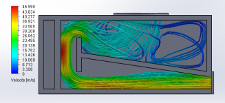
This is just simple simulation software. The results could be different with some expensive simulation software
edit: this image is the same as the last, but with both sides open
This is just simple simulation software. The results could be different with some expensive simulation software
edit: this image is the same as the last, but with both sides open
Attachments
Hi,
It's a lot more complex simulation software than what I have access to. Thank you very much. The question I have is, how does steady flow compare to pulsating pressure progapation? Or is that already part of the simulation?
Regards,
It's a lot more complex simulation software than what I have access to. Thank you very much. The question I have is, how does steady flow compare to pulsating pressure progapation? Or is that already part of the simulation?
Regards,
This is just one push of air. I don't think I can simulate pulsating pressures. You mean a simulation where the cone moves up and down at a certain frequency, right?
So I was bored and wanted to know the use of corner pieces in a transmission line box.
I already had a model in Solidworks so decided to do a flow simulation here.
I've attached a image of what the program calculated.
One is with corner pieces, and one without.
So can I say the corner pieces are sort of useless for the airflow?
Or is there an other advantage why everyone should use them?
Interesting stuff.
Shouldn't the flow "start" from where the driver is though, rather than from one end of the TH?
Can you model the flow in other types of TH folds, like the one used in the SS15, for example?
Hi Brian,
Michelp89's enclosure is a TL w/ reducing cross-section. This is quite interesting, isn't it?
Regards,
Michelp89's enclosure is a TL w/ reducing cross-section. This is quite interesting, isn't it?
Regards,
Hi Brian,
Michelp89's enclosure is a TL w/ reducing cross-section. This is quite interesting, isn't it?
Regards,
Ah, it's a TL, not a TH. I misread the post.
What's interesting to me is the low-pressure cavity right after the bend. I wonder if there's any way to address that by changing the geometry of the bend, and if that change would actually make any significant difference...
Nice to see how the airflow (OK based on one pulse) within a TL develops...
I guess the software will be very useful in designing the interior of loudspeaker boxes in such a way that pressures are as evenly spread as possible.
Now a copy of Solidworks...😀
I guess the software will be very useful in designing the interior of loudspeaker boxes in such a way that pressures are as evenly spread as possible.
Now a copy of Solidworks...😀
Nice to see how the airflow (OK based on one pulse) within a TL develops...
I guess the software will be very useful in designing the interior of loudspeaker boxes in such a way that pressures are as evenly spread as possible.
Now a copy of Solidworks...😀
$4K per license, $1.3K p.a. in support...
Oof.
can the model partly examine this case with a 27 sq.in. vent that feeds front chamber?
An externally hosted image should be here but it was not working when we last tested it.
An externally hosted image should be here but it was not working when we last tested it.
I was just thinking.. It is not one pulse, but a constant stream which I am simulating. But I don't think the results will be very different. Maybe it even shows a more useful result right now.
I'm at work right now so I will do the simulations at about the same time as yesterday
I'm at work right now so I will do the simulations at about the same time as yesterday

- Status
- Not open for further replies.
- Home
- Loudspeakers
- Subwoofers
- Transmission line 'flow simulation'