Not sure what I can tell you now, but the test of "conduction" of Q1207
could have been answered by checking the voltage on R1211 as said.
The difference between channels you noted here is no indication of fault.
The observation that there was clipping in neg voltage only led me to
contemplate about where it happens in the circuit, but it was a guess only.
If you can power up both channels without harm we may be able to find
the reason of malfunction with some more test results - voltage checks.
Not sure what I can tell you now, but the test of "conduction" of Q1207
could have been answered by checking the voltage on R1211 as said.
The difference between channels you noted here is no indication of fault.
The observation that there was clipping in neg voltage only led me to
contemplate about where it happens in the circuit, but it was a guess only.
If you can power up both channels without harm we may be able to find
the reason of malfunction with some more test results - voltage checks.
Very good, I really do appreciate the assistance you’ve provided, a literal life saver! I can power up both channels at the same time, the voltages I have checked are fairly similar in all the places I checked. Maybe I should turn up the volume until a good amount of that clipping on the bottom side of the waveform and then test voltages? The dummy loads are 1000w rated resistors on heatsinks so they could likely take the abuse.
If all else fails I was thinking of just swapping like five components at a time between each board and stop one the issue shows itself lol.
One thing I questions and maybe you can answer. How come it makes more clean power on lower voltage/current?
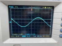
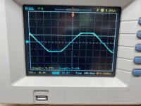
Plugged into the wall on line voltage the bad channel starts the clipping on the bottom of the waveform at 5v which is just over 3 watts.
Plugged into the variac and dim bulb tester it makes more. I have the variac set at 119v and once through the dim bulb tester the receiver is seeing 106V when it is powered up. On that lower voltage both channels clip equally on both the top and bottom of the wave. They both produce a clean 9.2V before any clipping, so 10-1/2 watts.
So just don’t know how that works, on more voltage and current you only get 3 watts, but on less wattage and current you get 10.5 watts.
I’m going to continue on, but if you have any place you think I should check first let me know.
Thank you!
Dan
Attachments
Last edited:
We need more dc voltage checks, starting with the supply.
Yes, under load and at a level where clipping is clearly seen.
Is it true that the clipping occurred without load also ?
Check R1231 again and move the wiper in this case after the
initial position has been marked, watch the scope.
This applies only if your observation is true : fault is on driver
board. Check R1307, Q1303, Q1305, maybe CR1303 otherwise.
Operation at half of mains voltage does not count here.
Last edited:
We need more dc voltage checks, starting with the supply.
Yes, under load and at a level where clipping is clearly seen.
Is it true that the clipping occurred without load also ?
Check R1231 again and move the wiper in this case after the
initial position has been marked, watch the scope.
This applies only if your observation is true : fault is on driver
board. Check R1307, Q1303, Q1305, maybe CR1303 otherwise.
Operation at half of mains voltage does not count here.
The supply voltage, measuring at the filter caps is a +35.74 Vdc and -35.81 Vdc. At the actual driver board
The good channel:
At 1209 I have 35.46 V
At 1215 I have -35.38 V
The bad channel:
At 1209 I have 35.48 V
At 1215 I have -35.44 V
At 1204, both channels are the same, start at +28 V and as I bring the volume up into heavy clipping it drops to +27, +26, +25 V and both channels drop equally.
As I bring the volume up both the positive and negative rails drop to 34 V then to 33 V, both channels drop equally. If there is somewhere else I should check supply voltages let me know.
Dan
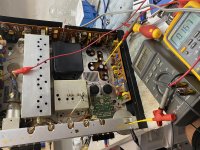
Well.... hmmm.... did I do something wrong? I wanted to measure the +/- base and +/- emitter so I soldered some flying leads to those test points. Hooked up a pair of meters, connecting the negative probe to the chassis and the positive to the + base of each channel. Set my meter for DC voltage and.... now I have no output at all from either channel. Both channels are dead. I measured the output of the preamp and the signal is still getting the input of the driver boards and I measured the rails and still have the +/- 36 V on both boards.
Can I not measure the base or emitter? Should I not have put my meters onto the chassis. I’m going to tear them down and measure the outputs. Ugh.
P.S. there is also a funny metallic smell in the air...
Dan
Can I not measure the base or emitter? Should I not have put my meters onto the chassis. I’m going to tear them down and measure the outputs. Ugh.
P.S. there is also a funny metallic smell in the air...
Dan
Attachments
Well I just checked the output and the drivers that are mounted to the heatsink and they all measure just fine on a Peak Atlas DCA75.
Dan
Dan
Well I’m not sure what is going on obviously, but left it overnight and decided to look at it with fresh eyes. I left the bad channel dismantled, but still left the circuit whole so I could monitor it. Well wouldn’t you know it, the good channel now has output again. The bad channel is still completely dead so now to trace a signal. Let’s hope that whatever was causing the clipping issue is what went up in smoke and I can get a good signal.
When I get signal to the output once again, is there any harm in monitoring the +/- base or +/- emitter with a dmm and negative probe on the chassis?
Dan
When I get signal to the output once again, is there any harm in monitoring the +/- base or +/- emitter with a dmm and negative probe on the chassis?
Dan
Not sure what you did and what happened.
I think I showed you a way but you choose
a different path - I am fine with that but am
afraid I can not follow.
I think I showed you a way but you choose
a different path - I am fine with that but am
afraid I can not follow.
Not sure what you did and what happened.
I think I showed you a way but you choose
a different path - I am fine with that but am
afraid I can not follow.
I’m not entirely sure what happened either, but I let it sit for a few days and what do you know, I’m back to where I was. Good output on one channel and output that clips on the bottom side of the other.
I didn’t mean to go a different direction than you had suggested, I was just trying to make testing points so that I could monitor the voltage on the board. Since I’m back to where I was at I’ll go back to where you last assisted me. I’ll check R1231 again. The trimmers have been glued into place, I’ll mark them with a sharpie before adjusting.
You suggest looking at R1307, Q1303, Q1305, and CR1303. How would those effect the driver board specifically? If I swapped the driver boards and the issue followed the swap wouldn’t the issue be on the actual driver board and not the power amp board? I’d figure if the waveform was good before the driver board swap that the amplifier board would be good.
Dan
If you are sure the driver board is faulty :
- R1231 sets negative current limit.
- Adjustment range is small, but the pot has to be ok.
- Does the clipping occur without load also ?
- if so check Q1207, Q1208, R1221, CR1203;
- expect about 1.8V on CR1203, 1.2V on R1221.
- Neg.output is driven by Q1204, it must be fine to do that.
- R1231 sets negative current limit.
- Adjustment range is small, but the pot has to be ok.
- Does the clipping occur without load also ?
- if so check Q1207, Q1208, R1221, CR1203;
- expect about 1.8V on CR1203, 1.2V on R1221.
- Neg.output is driven by Q1204, it must be fine to do that.
So are the driver boards in some way tied to the time delay board? This receiver is trying to defeat me I know it. I’ve never had trouble as I’ve had on this unit.
So I had output from both channels. I dismantled both channels so that I could bend the boards back in order to remove the small wire leads I had placed for monitoring the base and emitter voltages and then put the two channels back together. All I did was remove the leads. Powered it back up and again lost the output from both channels. Ugh!!! I check and see no shorts of any kind (wires to the chassis, long component leads, etc) and it doesn’t look like any wires have broken free from their soldered posts.
So I power it back up (this entire time powered on a variac and dim bulb tester) and confirm that I do not have audio output. So I put my scope leads to the inputs of the driver boards and see that I have perfect looking waveforms going to each driver board.
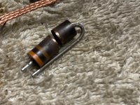
Then I see the dial lights go out and smoke billowing out of the chassis!!! What the heck!!! I see where the smoke is coming from and find a board hidden, the time delay board. The only thing burnt on the board is R1404, a 68 ohm 1/2 watt resistor.
So now I’ll pull the board, replace some components on it and go from there.
So my question, would the time delay board in any way effect the dial lights or audio output? Running a sinewave through a function generator through aux input. If not then i have to figure out why I’m losing audio from both channels by simply touching a soldering iron to three points to remove leads and bending boards out of the way. I can’t let this defeat me.
Dan
So I had output from both channels. I dismantled both channels so that I could bend the boards back in order to remove the small wire leads I had placed for monitoring the base and emitter voltages and then put the two channels back together. All I did was remove the leads. Powered it back up and again lost the output from both channels. Ugh!!! I check and see no shorts of any kind (wires to the chassis, long component leads, etc) and it doesn’t look like any wires have broken free from their soldered posts.
So I power it back up (this entire time powered on a variac and dim bulb tester) and confirm that I do not have audio output. So I put my scope leads to the inputs of the driver boards and see that I have perfect looking waveforms going to each driver board.
Then I see the dial lights go out and smoke billowing out of the chassis!!! What the heck!!! I see where the smoke is coming from and find a board hidden, the time delay board. The only thing burnt on the board is R1404, a 68 ohm 1/2 watt resistor.
So now I’ll pull the board, replace some components on it and go from there.
So my question, would the time delay board in any way effect the dial lights or audio output? Running a sinewave through a function generator through aux input. If not then i have to figure out why I’m losing audio from both channels by simply touching a soldering iron to three points to remove leads and bending boards out of the way. I can’t let this defeat me.
Dan
Attachments
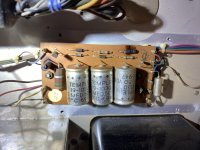
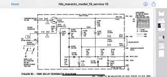
Actually R1407 from that board was crisped a bit as well and fell into two as soon as I touched it. Not sure of that was from when I had it powered up it started smoking or from the years of use, but the charting on the board leads me to think it’s from years of use.
Dan
Dan
Attachments

I rebuild this audio delay board and I was being cautious obviously, but I powered it up on the dim bulb tester and had it on for maybe 3-4 seconds at most and then powered it down. I checked the temp if R1404 and it was blistering hot. I put a 1 watt resistor in place of the old 1/2 watt and I couldn’t get my finger off of it fast enough it was so hot. What could cause me to lose audio in both channels and cause that resistor to get so hot?
Looking for the obvious I started checking the driver boards for shorts.
At 1204 for the +28v I have a dead short showing up on both boards
At 1206/1212 I have a dead short, not sure if that’s okay there or not.
At 1209 for the +36V I measure 65 ohms to ground on both driver boards, seems very low.
At 1210 for the + emitter I measure 65 ohms to ground
At 1213 for the amplifier output I measure a short on one board and 220 ohms on the other.
So I’m obviously looking for the shorts...
Dan
Of course, pinched wires from reassembling the side driver and amplifier boards...
R1404 is no longer getting hot as I don’t have a short to ground on the +28V rail any longer.
And I now have output on both channels now...
Dan
R1404 is no longer getting hot as I don’t have a short to ground on the +28V rail any longer.
And I now have output on both channels now...
Dan
If you are sure the driver board is faulty :
- R1231 sets negative current limit.
- Adjustment range is small, but the pot has to be ok.
- Does the clipping occur without load also ?
- if so check Q1207, Q1208, R1221, CR1203;
- expect about 1.8V on CR1203, 1.2V on R1221.
- Neg.output is driven by Q1204, it must be fine to do that.
The clipping does occur with no load on the outputs, but does not occur when current limited on the variac/dim bulb tester.
I check the devices you suggested and it is without a doubt Q1208, thank you!!!
I swapped them between the channels and sure enough the issue swapped channels. I measured it like 5 times on my Peak Atlas DCA75 Pro transistor tester and it tested out perfect every time. So no I need to find a replacement for a MPSA56.
Dan
I thought I’d run some possible replacements by you if you don’t mind
MPSA93 or MPSA92, I have hundreds and according to alltransistors they are more robust.
ZTX796A, again looks more robust.
BC556
Those look to be the best candidates.
If anyone has input on the best replacement that would be great! Just trying to use something I already have.
Dan
MPSA93 or MPSA92, I have hundreds and according to alltransistors they are more robust.
ZTX796A, again looks more robust.
BC556
Those look to be the best candidates.
If anyone has input on the best replacement that would be great! Just trying to use something I already have.
Dan
MPSA56 should be available in the neighbourhood also.
Oh I also have the 2N5401
I’ve read in places that each of these would make a good replacement except I haven’t seen anything on the ZTX, just the MSPA92, MSPA93, 2N5401, and BC556.
I’m hoping to replace the MPSA56 with one of them as I don’t have any on hand and tons of the others on hand. I figured if any of the others would make a suitable replacement then I could avoid paying $10 in shipping charges and 5-6 days for shipping. I’ll put the MPSA56 and it’s complement on my list for a future.
Dan
- Home
- Amplifiers
- Solid State
- Transistor subs for Marantz Nineteen driver board