This goofy circuit has no miller capacitor near R7. I suspect the circuit didn't make it to the checkout floor. 10 pf b-c caps, ha!.
A cap around R7 isn’t a “Miller” cap. It would be a lead compensation cap. The amp may or may not be stable without one. I tune these in by experiment on ALL builds anyway. Use a dim bulb, check the frequency of oscillation, see how much phase lead in the feedback you need. Analyzing it in Spice of you’re so inclined. I can dial it in by hand faster than setting up the simulation which is at the mercy of the model accuracy anyway. Try finding a 2N6259 model, I dare you. Just a hand drawn asymptotic Bode plot with estimates for where the poles are is all I ever use for audio amps. Just make sure G and H intersect with a slope difference of 6dB per octave not 12. If it sounds complicated it is. If my method sounds oversimplified to someone who simulates everything to within an inch of its life and believes the result blindly or calculates everything longhand in Mathcad, it is. It’s also not impossible to stabilize this type of amp even if you don’t understand the math. Takes a little longer and some patience.
When I do use them, I connect between the feedback summing node (R7) and the *output of the VAS*, not the speaker output. This pushes the non dominant pole frequencies caused by the driver and output transistor fT’s up higher by lowering the VAS output impedance at high frequency - in addition to what the Miller cap does. You also bypass some of the phase lag caused by the outputs. A little more high frequency distortion, a LOT more stability margin is possible. Fine for big PA or subwoofer amplifiers.
The 10 pf miller caps *are* a little small. 33 to 100 pF is more like it. But that TIP42 in the current mirror has a large Cob. In that position it has the same effect as the Miller caps on the lower diff pair. Remember, it is mirroring the current of the “cold” side of the pair so it’s Miller effect is transferred. It would be *better* to use the right transistor in the mirror and increase the 10 pF caps, but the circuit likely worked for whoever built it first. They probably didn’t even understand why.
Builds like this are often at them mercy of the build techniques and transistors substituted, so don’t think of it as a complete failure if it oscillated the first time. Use it as an opportunity to learn how to fix oscillations. Use those rugged output transistors and a dim bulb when starting it up and you will not blow it up if it does.
I have some old RCA transistors that look exactly like this - these 2N6472 and 2N6247. I have used 2N3773 in an early amplifier build this was a Motorola equivalent. The compensation scheme involved a 220pF capacitor from the Vas back to the inverting input terminal. The collector load was a bootstrap capacitor. The supply rails were +/- 50 Volts. The closed loop gain (over unity) was 22 times.
In the proposed circuit this is 33 times so phase will start to shift from a lower frequency and the compensation capacitor value would need to be increased accordingly. Furthermore there is no output inductor.
The power rating for 2N6259 is 250W compared to littlest brother sized 2N3773 at 150W and the collector current to collector emitter voltage is better.
The circuit I built had load line short circuit protection which is absent in the proposed circuit and there are no supply rail or output fuses.
It seems the thinking is to put the amplifier in the sub-woofer box to avoid risks of a short circuit damaging the amplifier.
These 2N6259's have been laying around for decades so why use just two of the four available.
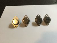
I posted that for reference, in case OP needs help deciding if his are real or fake. I have about 40 of these (all of them pulls) - saving then specifically for rebuilding any old Bose 1800/1, BGW500/750, or Phase Linear 400 or similar amp I might run into in my lifetime. Some of my stash has already found it’s way into those old amps. New construction I use MJ15024 or 21194 -as all my new stuff has complete SOA protection. The 6259 is one of the *only* transistors proven to survive without it (or with minimal protection). The others are all Japanese, and even harder to come by these days.

Signetics had an S logo like that but a black letter (not white on black background). But I think they were taken over by Philips before 1980?, which is the date code. Not sure, because Solitron also may have had a logo like that. Solitron is still going but no sign of a 2N6259 - these old devices are slow, and many stopped producing them at least on the original process (hometaxial or a near equivalent) by about 1980. They look genuine but they're certainly not RCA. They are probably the last of the species and only available as NOS (very expensive; an MJ21194 would be better) or pulls.
If you want the best out of them it might be worth driving them with modern drivers such as MJE1503x) (TIPs are no use) and use a low base-emitter resistor to help them respond more quickly. 200kHz fT is really slow but these can be made to work with a high base drive (blow and suck) but in quasi configuration, suck means a low base resistor.
If I had any I may even be tempted to build a "simple" SOA tester. Basically, use a fast MOSFET in series with the emitter and a spike detector also connected to the emitter (using a current sense resistor) that would trigger the MOSFET off if the current were to suddenly increase. If you can shut the device down (the base circuit also needs a protection diode to become disconnected too to prevent a C-B short) within say 1 us the device MAY still work, but the idea is to check that it survives the published RCA datasheet rather than test what its SOA actually is.
Perhaps someone in the community might even have a datasheet for these "other" manufacturers' high power devices.
Another suggestion - it is not too difficult to test for the fT. Set up a standard bias circuit but Ic=1A and feed a 50kHz signal into the base using an effectively constant current source (typically I try to modulate the base current by 10% of the DC value) and see what collector current you measure across a low value sensing resistor.
The min. gain should be 4, if significantly higher the device you have MAY be epitaxial (RCA changed from hometaxial to epitaxial for many devices around 1978) and may nto be quite so rugged.
The min. gain should be 4, if significantly higher the device you have MAY be epitaxial (RCA changed from hometaxial to epitaxial for many devices around 1978) and may nto be quite so rugged.
Solitron made lots of those old Hometaxials back in the day. I have a bunch of their old 3055’s, and used to have 3773’s before I used them all. Plenty rugged. May not be the proprietary “Hometaxial” process, but were at least a version of single diffused (where the Home part of it comes from).
This is the sort of thing that I mean by “pulls”. If they are in equipment that was working, they’re almost guaranteed not to be fake. Back in 1980, fakes weren’t rampant anyway. I could buy Toshiba C3281’s and D424’s from anybody that had them and get real ones.
This is the sort of thing that I mean by “pulls”. If they are in equipment that was working, they’re almost guaranteed not to be fake. Back in 1980, fakes weren’t rampant anyway. I could buy Toshiba C3281’s and D424’s from anybody that had them and get real ones.
So, i will use them. Thanks for all the info i really appreciate everybody s time.
Should i also add a choke to the amps output or it isnt necesarry?
it already has a zobel network.
Should i also add a choke to the amps output or it isnt necesarry?
it already has a zobel network.
Personally I don’t use the damped chokes, usually because I’m running #10 wire to my speakons and want to drive bridged 4 ohms. Is certainly not going on the board. They can always be added later at the speaker terminal if it ends up needing one. Zobels, always. With this output transistor, especially paralleled, you may want to use a lower “impedance” zobel than you would use for C5200’s. Maybe 4.7 ohms and .22 uF instead of the usual 10 ohms with 0.1. I’ve had to use as much as 1uF/2.2 ohm zobels, but that’s with 6 or more outputs in parallel and sub-2 ohm loads. It pretty much scales with maximum loading.
The 10 to 15 turn inductor on the output of an amplifier keeps RF from coming in the speaker jack and causing interference and oscillation. The S100 organ amps I worked on were picking up AM sports talk radio. Putting the inductor close to the speaker jack shortens the antenna (wire) transmitting inside the chassis. The organ has 20' of speaker wire. If your speaker wire is 6" you might get away without having an output inductor.
Those S logo parts, I used to see them in Lambda DC power supplies & maybe Power-one. Too obscure to be worth counterfeiting. Solitron maybe?
Those S logo parts, I used to see them in Lambda DC power supplies & maybe Power-one. Too obscure to be worth counterfeiting. Solitron maybe?
Last edited:
- Home
- Amplifiers
- Solid State
- Transistor replacement