transistor works very well. Collector resistor should be slightly larger to compensate for hfe signal loss. ie some of the drive current is present on the emitter resistor.
A small mosfet will balance the currents.
transistor bias voltage should be closer to 100v to get 60v p-p delivered to the driver tubes
A small mosfet will balance the currents.
transistor bias voltage should be closer to 100v to get 60v p-p delivered to the driver tubes
Last edited:
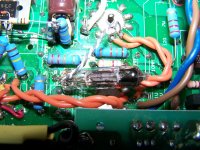
Nah--Pulled the Transistor, and bunged a Tube in its place.....
(Wire-ended 6C3B-V,--bit like a 6SN7ish,--one for each channel)
22K cathode/anode resistors, then DC Coupled to the gain stage, 12AX7/ECC83 dual triode--which is strapped in Parallel and with a MOSFET on top, signal taken from the source!
Deleted the cathode decoupling cap from first stage too.
Also changed the G1 resistors of the EL84 from 220K to 820K, and the cathode-resistors of the EL84 to 220 ohm.
Now its sounding Nice!
Last edited:
- Status
- Not open for further replies.