"TWO to replace"
Umm, isn't this a stereo amplifier with TWO channels, Land R?
I also wonder if the schematic just has the two Concertina resistor values swapped (typo).
Umm, isn't this a stereo amplifier with TWO channels, Land R?
I also wonder if the schematic just has the two Concertina resistor values swapped (typo).
Wouldn't need swapping if there were a PNP making it a Sziklai pair.
The smaller resistor of the totem would then be at the PNP's emitter.
Else I'm guessing in the dark the mystery extra transistor?
Then again, PNP+NPN Sziklai would appear to draw less base current.
Those resistors could be more equal than 39K 47K. The only excuse
for having made them unequal to begin with: is a large base current.
If there is a PNP here (or if we add MPSA92) need to be cautious of
the phase reversal's effect upon the global loop. Perhaps swap the
wires that drive the output grids would return things rightside-up.
Anyways, PNP here solves a few problems without changing other
parts already in circuit. Operate the splitter above B+/2, with the
first emitter pointed toward the high side.
Last edited:
Finding a complete service manual is about impossible, especially in English. Slickpepper.org.uk hasnt been up in a looooong time, and even then it was about impossible to verify what and where their sources were from... The closest reliable dealer Canadahifionline (tabnaac on Ebay) has never sold one and even as helpful as the guy is, he always had to do direct Chinese to English translations of any owners manual (service manuals about as fleeting as flying pigs). Grant Fidelity will not help even if they wanted to, as usual.. so..
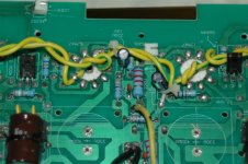
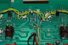
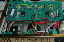
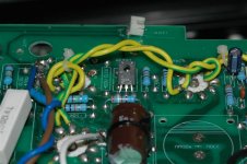
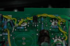
- You can see the two 669's. Even the pcb has direct, simple arrows pointing to their locations.
(For a humorous sidebar, the users manual is one simple page as to where you would plug the power cord and source inputs and speakers outputs. Really ridiculous).
The pics are to show the dual ecb 669's. Dont mind the two missing "chassis caps". Had to remove them to get the pcb up and over...
Attachments
Yup, stereo... Thats why two, nothing fancy to see here.
What DC voltage you measure at the base (or emitter) of either transistor at idle?
For purpose of determining if we are above or below B+/2, not for my next worry.
Maybe just Hitachi spec, but I looked up 2SD669A, only rates 160V CE? Go Figure...
Obviously if this transistor it hasn't blown up before now, must be alright with it?
ecb is "emitter collector base" simply referring to pinout.
Last edited:
With no transistor: I'm calculating 200V across the lower triode and 100V across
the top at maybe 0.5mA. This is way above B+/2! Once we connect the 2SD669A,
it will rise to B+/2 and become fully saturated, the voltage will then lock at B+/2
as the base begins to leak horribly into the emitter. I just don't see how it works.
You could go with MJE350? PNP 300V 20W Same ecb pinout, but you would still
have to twist and reverse the order of collector and emitter because its a PNP.
PNP emitter should orient toward B+, the collector should orient toward ground.
Now the splitter is happy with operating point at 200V, but PNP phase is wrong for
this global feedback loop. Either disconnect global feedback, swap connections to
output tube grids, or swap all four plate and screen wires of the output xformer.
Choose only one fix for the global feedback phase issue, not suggesting all three.
Last edited:
It should be safe to measure voltages with the transistor out of circuit.
This should confirm proper operating point of the SRPP without leakage
into the NPN base interfering with that measurement.
This should confirm proper operating point of the SRPP without leakage
into the NPN base interfering with that measurement.
Shunt 4.7K strapped across MJE350 base to emitter junction
could source an extra 0.66V/4.7K=0.15mA for the lower triode.
Bringing that 200V operating point up to 225V, the sweet spot
for PNP concertina at (3/4)B+. Assuming B+ is 300V after the
2K2 + 22uF lowpass filter.
could source an extra 0.66V/4.7K=0.15mA for the lower triode.
Bringing that 200V operating point up to 225V, the sweet spot
for PNP concertina at (3/4)B+. Assuming B+ is 300V after the
2K2 + 22uF lowpass filter.
OK, I figure at this point you might want or need a picture of my thoughts...
Notes:
MJE350 PNP needs collector and emitter swapped. Longer leads might help.
If you cram ECB into the same holes as marked for NPN, a PNP won't work.
Drives lines to Pentodes swapped (not only way to fix, but easiest to draw).
Base driven from bottom end of R1 1K rather than top.
Mainly so extra 0.15A can be shunted thorough R4 4K7 without confusing V1B.
This extra current should bring V1A's operating voltage up to 225V = (3/4)B+.
If you choose not to add the 4K7, which end of R1 doesn't matter so much.
You'd still have a valid 200V operating point for driving the PNP concertina.
These location designators probably do not match those of Yaquin's board.
Only intended for comparison to the original schematic.
Consider changing R6 to 39K, or shunting 250K across the existing 47K.
Attachments
Last edited:
What if to solder instead of transistor something like 6J32B in triode mode, it has flexible legs... Or paralleled both sections of 6N16B?
''Èñòîê2''. Ðàäèîëàìïû - ïî÷òîé. Ïàðàìåòðû è õàðàêòåðèñòèêè 6Æ32Á
''Èñòîê2''. Ðàäèîëàìïû - ïî÷òîé. Ïàðàìåòðû è õàðàêòåðèñòèêè 6Í16Á
''Èñòîê2''. Ðàäèîëàìïû - ïî÷òîé. Ïàðàìåòðû è õàðàêòåðèñòèêè 6Æ32Á
''Èñòîê2''. Ðàäèîëàìïû - ïî÷òîé. Ïàðàìåòðû è õàðàêòåðèñòèêè 6Í16Á
What if to solder instead of transistor something like 6J32B in triode mode, it has flexible legs... Or paralleled both sections of 6N16B?
''Èñòîê2''. Ðàäèîëàìïû - ïî÷òîé. Ïàðàìåòðû è õàðàêòåðèñòèêè 6Æ32Á
''Èñòîê2''. Ðàäèîëàìïû - ïî÷òîé. Ïàðàìåòðû è õàðàêòåðèñòèêè 6Í16Á
Doesn't fix the problem of SRPP direct coupling into N splitter above B+/2.
If that 6J23B comes in P flavor, hook me up with a dozen.
Would need to knock SRPP operating point down to 75V for optimum N split.
Anything less than 150V might "work" for N's including that Triode you posted.
But I calculate 200V in Yaquin's drawing poses a problem for all N types.
Easier fix is P split. Fine for direct couple at 200V, optimum at 225V.
Trying not to hack up the board...
Last edited:
Doesn't fix the problem of SRPP direct coupling into N splitter above B+/2.
If that 6J23B comes in P flavor, hook me up with a dozen.
Shift level by resistive divider, upper resistor shunted by cap.
Yes, simple fix for DC operating point. But adds another capacitive pole in the GNF loop.
Slightly increased risk of oscillation instability... Might work, might not...
Slightly increased risk of oscillation instability... Might work, might not...
Last edited:
In least invasive version of PNP fix, you change transistor for a bent up PNP
and swap orientation of four output transformer wires. No board traces cut.
The operating point won't be optimal, but it will be valid. And the splitter will
then actually work as was probably the original intent.
and swap orientation of four output transformer wires. No board traces cut.
The operating point won't be optimal, but it will be valid. And the splitter will
then actually work as was probably the original intent.
Last edited:
Might work, might not...
Depends on how close are poles to each other. No problems at all. Williamson works, by the way.
And mind you: if those NPN transistors bolted down? Might also be an electrical
connecton to the collector.
MJE350 PNP usually has a metal back, exposed collector, so be wary of that...
Especially since you gotta swap connections: Collector for Emitter.
connecton to the collector.
MJE350 PNP usually has a metal back, exposed collector, so be wary of that...
Especially since you gotta swap connections: Collector for Emitter.
Depends on how close are poles to each other. No problems at all. Williamson works, by the way.
So I've heard...
Is Yaquin OPT good enough for Williamson with complete stability?
I'm not saying your fix won't work, just adds another pole to the
unknowns of the transformer. Which one becomes the dominant?
One low pass has to roll below unity loop gain before any others
(including unexpected parasitic ones) can compound phase shift.
(Total shift less than Invert+120 < 300) Whats your plan?
Last edited:
As I said, depends on value of the capacitor. Plus, since it is shunted by resistor... Think of phase shift. 😉
I would use 6N16B: it is a miniature version of 6N1P. One more option is to use upper tube for Concertina instead of dynamic load, and use transistor as gyrator instead of the upper tube.
I would use 6N16B: it is a miniature version of 6N1P. One more option is to use upper tube for Concertina instead of dynamic load, and use transistor as gyrator instead of the upper tube.
- Status
- Not open for further replies.
- Home
- Amplifiers
- Tubes / Valves
- Transistor phase splitter (Yaqin MC-84L)