Trying to repair a sfa 1800.5 and it has a couple blown transistors marked c1. 4.7 ohm gate resistor. Would this be the irf530n? Thanks


Or would this take the 4127? Same marking. But this is a 5 channel didn’t want to fit the wrong thing thanks!
Switched them out and they’re running a lil warm and is it normal for the drive to look like this 

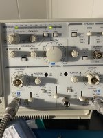
Without scope settings, it's hard to know what the images are showing.
It's hard to judge waveforms unless you're using a mains-powered scope in differential mode (using 2 channels as one).
Which part number FET did you use?
It's hard to judge waveforms unless you're using a mains-powered scope in differential mode (using 2 channels as one).
Which part number FET did you use?
I don't have a lot of information on this type of amp but more that use this output use the 3.3 ohm gate resistor.
Amp has 47 ohm resistors. I’ve tried the 4115s, 4127s and the 530n. I may have a problem somewhere else
The first post says 4.7.
Is the diode adjacent to the gate resistor connected in direct parallel with the gate resistor?
Do you know how to use your scope in differential mode?
Do both channels of the scope work?
Do you have two scope probes?
Is the diode adjacent to the gate resistor connected in direct parallel with the gate resistor?
Do you know how to use your scope in differential mode?
Do both channels of the scope work?
Do you have two scope probes?
they’re 47ohms that’s my fault was using a different dmm. Yes the diode is parallel with the resistor. And I never figured out how to use the 2 probes. When I set everything and test it on 12 volts the line on the scope drops a bit and just gets blurry
A differential input uses two inputs to produce a single waveform. The simplest way to get a differential input is to use a differential probe. A differential probe has two signal leads and a mixer amplifier built into it. It feeds the scope a normal signal (a composite of the two signals input into the differential probe). The problem with differential probes is that they're expensive.
The alternative is to use two scope probes and and both inputs of your oscilloscope. This is how you have to set up your scope:
Two probes
Both scope inputs used
Input set to add
Both channels set to DC coupling
Both channels set to 'cal'.
Both vertical amps set to the same voltage
Ch2 input set to invert
Bandwidth limited (works best for most measurements in car amps)
Trace aligned to the reference line on the scope's display
Ground leads for both probes connected together (not always necessary)
After setting up the scope, you need to confirm that it's working as it should. With the vertical amp set to 5v/div, touching the probe that's connected to Ch1 to the positive terminal of your 12v power supply should make the trace deflect about 2.5 divisions up from the reference (like it always does, seen below). Doing the same with the probe connected to Ch2 should make the trace deflect down about 2.5 divisions. Touching both probes to the positive terminal of the 12v power supply should cause no deflection. If it does, something isn't right.
I know that this may not be as simple as the isolated scope but if you take the time to learn it one time (even if it takes an hour or more of your time), you have that knowledge and this tool to use for the rest of the time you need to use a scope. Using the analog scope will give you much larger and cleaner waveforms.
These are the exact steps I attempted to follow. When I do everything and get to the part where I test it I’m not going there 2.5 divisions.
Is you 'var' knob set to the 'cal' position?
Are you having this same problem on both channels?
Scope v/div setting?
Scope probe setting (1x or 10x)?
Are you having this same problem on both channels?
Scope v/div setting?
Scope probe setting (1x or 10x)?
That's what it's supposed to do. If you align the trace with the reference, set the vertical amp to 5v/div and touch the ch1 probe to 12v, does it deflect up about 2.4 divisions?
If you touch both probes to 12v, does the trace go back to the reference line?
If you touch both probes to 12v, does the trace go back to the reference line?
It was a double line and blurry. I can’t even get it to do that now. I don’t know what 5 to use tried them all. I’ve went thru the steps a few times. Can’t get it set.
I don’t know what 5 to use tried them all. I’ve went thru the steps a few times. Can’t get it set.That's the timebase. Leave it at about 2ms.
I was referring to the vertical amplifier (one control per channel). Set it to 5v/div. Set the probe to 1x and touch the 12v supply positive. How far up does the trace deflect? Do this for channel 1.
I was referring to the vertical amplifier (one control per channel). Set it to 5v/div. Set the probe to 1x and touch the 12v supply positive. How far up does the trace deflect? Do this for channel 1.
- Home
- General Interest
- Car Audio
- Transistor marked C1 in Sundown SFB 1800.5D