@Brian Beck @Studley et. Al - In varying threads I see folks talking about building amps that are load invariant i.e. "work well with a dead short", etc, but nothing ever materializes or maybe it happens but nobody really posts about them. @lowmass
Is Colin Winfor still building things?
Mostly for us psycho ribbon guys. Niche as it is. Or maybe the latest high current (40a) Purifi modules using proper power supplies (cobra) ala buckeye amplifiers?
Is Colin Winfor still building things?
Mostly for us psycho ribbon guys. Niche as it is. Or maybe the latest high current (40a) Purifi modules using proper power supplies (cobra) ala buckeye amplifiers?

I'm only aware of one commercial amp that did this, Carver Sunfire? Anything else or DIY projects?
And that he accomplished by inserting a 2R2 power resistor in the signal path. That really are close to plain old cheatin` if you ask me.
R
R
Which amp are you talking about and where in the schematic is it? On the amp card or TDC?And that he accomplished by inserting a 2R2 power resistor in the signal path. That really are close to plain old cheatin` if you ask me.
R
The Sunfire,s have a current output choice with a big 1 ohm in series but nothing on the voltage outputs. Your choice
Right - so old school i.e. if the power supply can handle it, it doubles output when resistance drops?The First Watt F1 and F2 were current source amplifiers.
Is the whole transimpedence thing a marketing term or does it actually exist? Is it like an interface between the speakers and the output where it's simply padding it with resistance? Or is this a design choice and require more thought.
A couple of the M2x input stage daughter cards are transimpedance amplifiers (voltage in, current out), notably "IPS6". Builders seem very pleased with the way IPS6 drives the Edcor transformer primary in the First Watt M2 / M2x power amp. These are input stage "front end" cards, not loudspeaker driving power amplifiers.
_
_
Attachments
Do you have this in mind?
In a recent thread (that turned sour), the subject of "constant power amplifiers" (load invariant) was raised.
The usefulness or desirability or such a scheme is debatable, but there are more fundamental questions about the consequences of including such a "feature" in an amplifier.
In the thread in question (that I don't want to revive for obvious reasons), I said that this class of non-linear circuits was suitable for industrial control or processing, but not for audio.
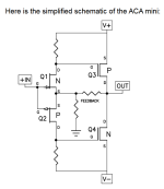
Here is what I mean by that.
The first pic below is such a device in its spice-idealized, canonical form. It is...
The usefulness or desirability or such a scheme is debatable, but there are more fundamental questions about the consequences of including such a "feature" in an amplifier.
In the thread in question (that I don't want to revive for obvious reasons), I said that this class of non-linear circuits was suitable for industrial control or processing, but not for audio.
Here is what I mean by that.
The first pic below is such a device in its spice-idealized, canonical form. It is...
I seem to remember Per Abrahamsen (RIP) of then Electrocompaniet named his 250W power amp as transimpedance with the understanding being a voltage input part and a current output part. However, the latter being a traditional emitterfollower output stage.
R
R
Welp I'm not trying to "open pandoras box" or anything as I understand it lots of smart people here going back and forth on what is better or not better more or less I'm trying to just see if people followed through with their statements of a few years ago (see original post). Every ribbon transducer thread seems to have one or two people that say "we're designing an amp load invariant class D (oopsie) amp" and then it vanishes.
What do you guys mean with load invariant power in this context? Constant voltage output, constant current output or constant power output witth changing load?
Jan
Jan
This is definitely a design choice. Adding R in series with a load just increases output resistance of your ordinary "voltage source" amp (most multi-way acoustic systems and subs won't like that) but you pay with output power! The larger the R you add > the more amp looks like current source > the less power is available for the load.Is the whole transimpedence thing a marketing term or does it actually exist? Is it like an interface between the speakers and the output where it's simply padding it with resistance? Or is this a design choice and require more thought.
Regarding design this all comes down to your load impedance. And power needed.
If your load impedance varies 6 ...10 Ohms and you need 25W - achievable in AB class.
100W for 2 ... 20 Ohms shoud be handled differently, G/H/D classes probably.
If you want the amp to be OK delivering 40A to short - ugh, D only, and not easy for DIY)
People rarely need transimpedance amp, that's why not many designs. I have heard of LM3886 based amp primarily for full range paper cone drivers.
Last edited:
I would say the latter (constant power output with changing load). Or more specifically not to care about the load and go into any protection mode?What do you guys mean with load invariant power in this context? Constant voltage output, constant current output or constant power output witth changing load?
Jan
That's two things. Constant power output with changing load is not a simple thing to achieve in an amp. You must keep the product of I and V constant with changing load. It means that if you deliver say 50W into 8 ohms, and you change the load to 4 ohms changing nothing else, the delivered load would still be 50W. Hard to do.
A protection circuit is just that, a protection system, limiting I and V to safe levels. It may also be set up to limit P of course. Is that what you mean?
Note that in normal operation, the protection system is always off so it would be invisible to the output, as if it is not there.
Jan
A protection circuit is just that, a protection system, limiting I and V to safe levels. It may also be set up to limit P of course. Is that what you mean?
Note that in normal operation, the protection system is always off so it would be invisible to the output, as if it is not there.
Jan
I shared a circuit on DIYA that achieves a defined impedance output similar to the Howland current source, but there is no output impedance that produces a constant power into any impedance, and clearly it is impossible to drive any power into a short or open. You can sense some combination of current + voltage but the result is not a constant power. You would have to multiply the two and positive and negative outputs would produce the same result. You would have to square the input for comparison plus the sign. And then there is the mater of speaker impedance variation with frequency. Dynamic (electromagnetic) speaker voltage reflects the cone movement, not power or current.
If someone has a circuit that they think is "load invariant", I'd really like to see that. Mark's circuit above is a constant voltage output because while the load is driven by high impedance collectors, the global feedback is voltage feedback, so the output is constant voltage.
If someone has a circuit that they think is "load invariant", I'd really like to see that. Mark's circuit above is a constant voltage output because while the load is driven by high impedance collectors, the global feedback is voltage feedback, so the output is constant voltage.
A current source is just that. For a given input, the output voltage is a function of the load impedance.
- Home
- Amplifiers
- Solid State
- Transimpedence Amps / Current source "load invariant"