I'm having some difficulty understanding the wiring diagram on this transformer. For the input, it looks like the BLK is 0 - RED is 115V and GRY is 0 - ORG is 115V. My assumption would be that the BLK and GRY go to the neutral side, while RED and ORG are the Hot side.
What confuses me is the label at the bottom --> N: YEL/GRN. To me this looks like it would for the shielding to ground, so why is it labeled with 'N'? Also, for 115V I would simply connect the BLK and GRY in parallel to neutral, and the RED and ORG in parallel to Hot, right?
One more question: The output on the transformer is labeled ORG 24V and BLK 24V. The input on my power supply has 2 2-terminal AC25V inputs. So, I would think that both ORG go to one of the input pairs, and both BLK goes to the other input pair. Correct?
Attachments
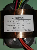
The transformer has two independent 115V primaries and two independent 24V secondaries.
The green/yellow wire is for a ground connection.
You have correctly described how to connect the two primaries in parallel to work on 115V.
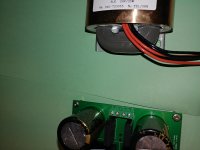
Not sure how the secondaries should be attached to the terminal strip on the power supply board since I can't see any helpful markings. Unlikely to be as you describe. I would have to be able to inspect the board closely from the track side.
Could post more information on the power supply board?
The green/yellow wire is for a ground connection.
You have correctly described how to connect the two primaries in parallel to work on 115V.
Not sure how the secondaries should be attached to the terminal strip on the power supply board since I can't see any helpful markings. Unlikely to be as you describe. I would have to be able to inspect the board closely from the track side.
Could post more information on the power supply board?
My guess would be that the two blacks go to the two inner terminals and the two oranges to the two outer terminals, but that is in need of verification!
We need to see the track side of the board or the schematic of the power supply board
We need to see the track side of the board or the schematic of the power supply board
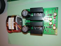
The pairs run individually to each rectifier. It doesn't appear to be center tapped. Let me see if I have the correct schematic somewhere.
On the transformer secondaries in the schematic, the black dots would indicate the orange wires. Does that help you trace the connections on the actual circuit board?
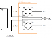
When I test for resistance on the transformer output wires I find that the orange-orange are connected and the black-black are connected. Wouldn't that indicate that each set goes to its own rectifier?
Check the secondaries with a multimeter. I would have thought each colour signifies a secondary.
edit, you beat me to it!
edit, you beat me to it!
Thanks SJ. Yes the two blacks constitute one secondary and the two oranges constitute the other secondary! I got that wrong!
Yes, it would appear that the two blacks go to one rectifier and the two oranges to the other!
Sorry for my diversion, but I think we've reached our destination! 🙂
And, you were right from the start! Shucks!
Sorry for my diversion, but I think we've reached our destination! 🙂
And, you were right from the start! Shucks!
Last edited:
I got it working. Thanks for your help. It sounds great, I'm going to let it burn in for a few hours before I make any judgments. Even without an enclosure (on an open test-bench) there is zero noise. I'll be glad to trash the Schitt Magni 3 it will be replacing.
Glad you got it working safely and that I learned something along the way - a double (good) whammy!
Usually the wires would have four different colours because if you were connecting them in parallel or together to create a centre tap it would be necessary to get the phase right

- Status
- Not open for further replies.
- Home
- Amplifiers
- Power Supplies
- Transformer wiring