I am looking at a Hammond 270FX transformer trying to figure out what B+ at what current I'll get with SS rectification.
The transformer Boiler Plate specs are:
BLK-BLK : 115 60Hz 138VA
RED-RED/YEL: RED 550VCT 150mA DC
YEL-YEL: 5V 3A
GRN-GRN/YEL-GRN: 6.3VCT 5A
If i subtract the filament power from the main VA rating:
138 - (5*3) -6.3*5) = 91.5VA
This should be the power available from the 550CT winding.
If I do SS rectification I get 550/2 * 1.414 = 388Vdc ignoring rectifier drop, etc.
So I should be able to pull 91.5VA/388V = 236mA of current from the supply.
This does not jive with what is on the boiler plate.
Unless the boiler plate is talking about 550 at 150mA in which case one would get 2* 150mA *225/388 = 174mA which still does not jive with the VA rating of the transformer.
The boiler plate does not agree with the published Hammond data which lists the 270FX as 138VA with 550VCT at 173mA which does jive closely with my second calculation.
So does one take the total voltage (in this case 550V) times the rated current and if FW CT one drops the voltage in half and doubles the current?
If this is true, then my Stancor P-6013 rated at 700V CT @ 120mA with CT grounded and FW rectification should produce 495V at 170mA.
This would support four 6L6s biased at 37ma (AB1) with 22mA for input tubes and drivers (Choke input to drop the B+ down to 450V would give even more margin).
No?
Furthermore, the Allied Electronics 6K49VG rated at 460VCT 50mA DC + 6.3V@2.5A should be be able to deliver 460/250*50mA = 92mA (choke input) at 250V B+, with 6.3V @ 2.5A.
No?
Last edited:
Absolute best thing you can do for yourself is get a copy of PSUD2 from Duncan Amps, learn how to enter the transformer model data, ie for FWCT, only half of the winding / voltage is used.
Hello TheGimp
The typical transformer VA rating is based on RMS true AC input and output. If the transformer does not have a resistance load start derating the capability of the transformer. Just for grins google K Rated Transformers. The K rating system is not for audio application but the concept of added transformer heating due to switching power supplies and harmonics will explain a lot. The more out of phase voltage and current, the bigger the spikes the more heat is generated in the iron. My rule of thumb is cut the nameplate VA by half.
Figure 20% voltage drop between unloaded and loaded conditions at the B+. Loaded may be closer to the nameplate voltage. Half loaded (yes pun) the voltage may be higher. Unloaded my be wow that is higher than I expected.
Yes if the 5 volt winding is not used the voltage regulation on the B+ may be better.
Or do it TubeLab style, load it until it sizzles then back off a little.
When you are finished hook it up to your FFT.
DT
All Just For Fun!
Gimp:
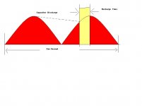
This most likely will be old info but are you aware of the current spikes you will encounter with SS rectification? Rule of thumb is current spikes of ten times load, or 200mA load will get you 2.2 A of spikes. SS is very hard on transformers..and lets not forget start-up surge. You would need a true OFF/START/RUN switch..or go with thermistors, or??
The point is SS has a very short time within the charge discharge cycle to firm up the voltages.
If you play around with Duncans fine SIM program you will see these parameters......I get a real kick out of tweeking the choices of values in the Duncan program...It can all fall under all the ratings if you just keep at it.
__________________________________________________________Rick....
Attachments
Talking about transformer regulation, I´m curious if a constructor specifies say 25% typical regulation, no load to full load. It means that the full load Vout (AC) wiil be the nominal, and at no load condition Vout will be higher, or the contrary (ie: the nominal Vout as advertised is the no load figure)?
Thanks
J
Thanks
J
DC watts will always be less than the VA rating, since the transformer RMS current includes the DC output AND the capacitor ripple current. A choke output may squeeze a few more watts out of a transformer (at a lower voltage of course) due to reduced ripple current.
It's a convenient rule-of-thumb that a FWCT rectifer will provide about as much DC current as the secondary RMS current. For a closer estimate, use Duncan Amps PSUD.
It's a convenient rule-of-thumb that a FWCT rectifer will provide about as much DC current as the secondary RMS current. For a closer estimate, use Duncan Amps PSUD.
Last edited:
Thanks all. A lot of this got prompted by the power supply I'm using in the FireFly amp. (Last listed Allied Electronics 6K49VG in my first post.)
I had picked up the Hammond 270FX transformer and looked it up on their web site and saw different ratings than are listed on the transformer which just confused me further.
With the Allied transformer, I'm using a choke input (Actually CLC with a small first cap) to allow the choke to spread the load over a greater portion of the ac cycle. This should reduce my peak charging current and slightly reduces IR loss within the transformer. By changing the first cap value I can tune the circuit for the desired output voltage.
I did model it with PSUDII and came out within 5% of the predicted voltage when I built the power supply so I figure it was pretty close considering component tolerances.
I currently have 120Vp-p across the inductor, so it is doing it's job well. I may clamp a current probe on it to see how much of the cycle the diodes are conducting.
I run thermistors in the ac input to help hold down inrush current at power on.
- Status
- Not open for further replies.
- Home
- Amplifiers
- Tubes / Valves
- Transformer Ratings