Exactly 😄 that's why I'm first trying to get some information would it worth of suffering to make it if after all won't work good. I have couple of them free and a lot of free wire around 1mm thickness. 😁Rewinding MOTs is a pain in the *** because the E’s and I‘s are usually welded together. Which means running the entire length of the wire through the core over and over and over again, potentially scraping the enamel off the wire each time thru. I’ve done low voltage secondaries like that but good luck with a primary. It’s just too many turns.
Yes I would like continuous power. By core size I guess I can get traffo around 500VA and that's good if it's possible.So basically you are asking whether a microwave transformer core can be used for a power transformer for continuous duty.
I guess it is, but probably only for low continuous power.
Getting a real continuous power core is probably cheaper/easier.
Jan
I've tried already to find only core or whole traffo but unfortunately for traffo of around 500VA I would have to give around 100$ which is just too much for me.
No no I wouldn't use sec as prim, I would take out windings completely and wind new prim and sec on just core of MOTHello Brko, if you mean to rewind both sections I think you would use it in a reverse way (prim->sec and sec->prim).
I wound many transformers but never microwave ones 1-2kV. Also, mind that one wire of the HV is connected to the transformer core so if you use plain the HV as primary beware that you have a live contact on power up.
That looks to me like a #19, which is good for about 2 amps in transformer applications. Based on core size for most MOTs you’d need about 2.75 to 3 turns per volt to get the flux density down to something normal so it doesn’t sound like a stalled electric motor while it’s running. If you have 120 volt mains that’s 360 turns. Double it for 240. I’m not even sure that would fit - without a secondary. If you run with less turns per volt, it will probably vibrate itself off the table and run hot. I would find a better donor core than a MOT. Something out of a junked receiver would be where I’d go looking. One with a plastic bobbin is far easier to work with - manual winding works almost as well as machine winding with them.Exactly 😄 that's why I'm first trying to get some information would it worth of suffering to make it if after all won't work good. I have couple of them free and a lot of free wire around 1mm thickness. 😁
I have seen this done (back to back mains transformers) in a turntable power supply for improved mains filtering reasons. The filter components
were operated at the lower in between voltage and could use larger value filter caps than would be wise to use on the mains voltage directly.
Ah I just remembered that the second transformer just stepped up the voltage to around 120V so not strictly comparable to what you want to do.
were operated at the lower in between voltage and could use larger value filter caps than would be wise to use on the mains voltage directly.
Ah I just remembered that the second transformer just stepped up the voltage to around 120V so not strictly comparable to what you want to do.
Last edited:
According to other forums and sites for calculating turns for 1v on my core is 1.7 turn (42 devided by core width 3.4cm times by core length 7cm) so I would need around 400 turns cuz main ⚡ is never going over 220v (not even 200v), I will have to precisely measure those holes than I can approximately know how much space will take for 400 turns and will there be any space left for secondary cuz I would like to get 30-0-30v which is around 100 turns more.That looks to me like a #19, which is good for about 2 amps in transformer applications. Based on core size for most MOTs you’d need about 2.75 to 3 turns per volt to get the flux density down to something normal so it doesn’t sound like a stalled electric motor while it’s running. If you have 120 volt mains that’s 360 turns. Double it for 240. I’m not even sure that would fit - without a secondary. If you run with less turns per volt, it will probably vibrate itself off the table and run hot. I would find a better donor core than a MOT. Something out of a junked receiver would be where I’d go looking. One with a plastic bobbin is far easier to work with - manual winding works almost as well as machine winding with them.
It would be for sure easier solution if I can get some broken amplifier on junk but unfortunately that's not happening in my country, no one doesn't wanna throw away it just sell it for price which is not worth to pay for something broken.
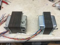
Both of these were salvage jobs custom rewound for tube amps in progress. End bells are new on the small one. The bigger one is 1.8 turns per volt, the smaller one 2.75. That’s what it took to get them quiet. The smaller one is about the size of your typical MOT.
Attachments
That + 1000It is sorta desperate way to get high voltage on a budget in the world dominated by the low-voltage solid-state electronics. There is a point in using two transformers with 6 or 12 volt secondary to get also the heater power, but if you intend to use separate transformer for this, than the isolation transformer (230V to 230V) might be more useful and economical.
It always struck me as a bulky wasteful "solution", only justified if you have a shoebox full of pulled/recycled small trafos ... and even so ....
This is an "official" design which got somewhat popular ...and even so notice +V consumption is minuscule, just a couple mA.
Suitable only for a Preamp (in this case a Guitar pedal) and not much else.

Rewinding, salvaging, using back-to backs make sense in places where you can’t import anything (like the relatively inexpensive Antek units) or you want something custom that would end up costing a fortune (like the ones in my pic - which was to give a sense of size vs. how many turns you need). Or if $28 really IS a barrier in your situation. At one time it was in mine. That’s when I was schooled in the art of trafo winding. It was either that or use 9 volt batteries.
But MOTs really are a poor choice to salvage. The only thing I’ve ever recycled them for were battery chargers (which would jump start a car). Took two in series to do it but they were free and I didn’t care that they sounded like a low flying plane when cranking. Of course I kept the original primaries.
But MOTs really are a poor choice to salvage. The only thing I’ve ever recycled them for were battery chargers (which would jump start a car). Took two in series to do it but they were free and I didn’t care that they sounded like a low flying plane when cranking. Of course I kept the original primaries.
Well after some thinking, conclusion is that is much better not to loose my nerves trying to rewind MOT, it's not really worth to waste wire and still is questionable am I gonna get good traffo or it will became some vibrating call from hell. 😁
But I did manage to find some thrown EI cores for around 250VA traffo and also I found one MOT which is surprisingly isn't welded completely like all others and I manage to take it apart EI and now I have one more maybe stupid question but I'm just a noob.
Is it possible to use cores from 2 traffo which are completely same and make 1 huge traffo which would be longer then wider, is there some rule for size of core which can't be broken for normal traffo or something like that is possible? I saw on yt some guy from India made traffo combining 3 smaller ones but I don't believe everything what is on yt. 🤔
Here is link from yt video:
Last edited:
That’s not the direction you want to expand in for making a transformer “bigger“. At least not by that much. You actually want longer “E’s” to make it perform better - there’s another thread concerning that. Stacking the bobbins two high and letting the E’s meet in the middle theoretically results in a better transformer - IF you can keep the air gap at the center minimized. Depending on how consistent the laminations are that may be a big if.
For sure I wouldn't go that long.That’s not the direction you want to expand in for making a transformer “bigger“. At least not by that much. You actually want longer “E’s” to make it perform better - there’s another thread concerning that. Stacking the bobbins two high and letting the E’s meet in the middle theoretically results in a better transformer - IF you can keep the air gap at the center minimized. Depending on how consistent the laminations are that may be a big if.
If I'm figured out well you are saying that would be better to make traffo wider where E's laminations doesn't cross each other like usually, only meet in the middle? If that would work I could do it.
I will check the other thread maybe there is more informations for learning.
hello!!! hope I am in the right place
and some of you can help me with this: I have a question that is driving me crazy!!! here’s the thing: if I have two secondaries in a out put transformer ( like sowter does 4 + 4 Ohm for example) in a 2 way speaker, can I connect a speaker, on each secondary? and what will be the impedance at the primary? example: 5k at the primary, 2 + 2 Ohms secondaries, 8 + 8 Ohms speakers. I much appreciate!!!
and some of you can help me with this: I have a question that is driving me crazy!!! here’s the thing: if I have two secondaries in a out put transformer ( like sowter does 4 + 4 Ohm for example) in a 2 way speaker, can I connect a speaker, on each secondary? and what will be the impedance at the primary? example: 5k at the primary, 2 + 2 Ohms secondaries, 8 + 8 Ohms speakers. I much appreciate!!!
With a proper crossover, only one or the other speaker is "seen" at a time.in a 2 way speaker,
Thank you PRR, but I really can’t see, the speakers are in parallel and they are seen even they are not concerned by the signal….proper crossover do you mean at
least 24db, and if I heard one note at the time?
least 24db, and if I heard one note at the time?
Last edited:
No. The result is general. If you send lows to one load, and highs to another load, with any reasonable division in the overlap, the total network impedance is "Flat".….proper crossover do you mean at
least 24db, and if I heard one note at the time?
If I use the "exact right" filter values, the line is dead-flat, and it looks like a trick. Here I have a 13% "error" in the coil value which gives a 6% rise of impedance at crossover.
Remember that the more the bobbin's central lamination hole differs from being square, the higher the windings' DC resistance and the lower the total efficiency will be.Is it possible to use cores from 2 traffo which are completely same and make 1 huge traffo which would be longer then wider, is there some rule for size of core which can't be broken for normal traffo or something like that is possible?
Best regards!
- Home
- Amplifiers
- Tubes / Valves
- Transformer questions