Try measure voltage between the three pins in the white connector in the middle of the board. That may be all you need.
What are you using as a reference when you measure these voltages? I am sure not every regulator on that board can have gone bad to the point of getting these weird readings.
What are you using as a reference when you measure these voltages? I am sure not every regulator on that board can have gone bad to the point of getting these weird readings.
I've been taking readings by moving my meter probes between the output pins on the board as shown in the photos I've posted. Should I be using a different ground reference? Thanks.
Try using the middle pin of the white connector in the middle as reference for all your measurements.
If you still have weird measurements, please post a photo of the rear side of the DENON board so we can identify the ground-plane.
If you still have weird measurements, please post a photo of the rear side of the DENON board so we can identify the ground-plane.
Try using the middle pin of the white connector in the middle as reference for all your measurements.
If you still have weird measurements, please post a photo of the rear side of the DENON board so we can identify the ground-plane.
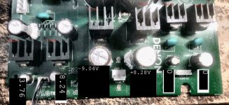
Measuring with the negative meter lead at the centre pin I get +8.28V at the right side pin and -9.04V at the left side pin. I've included a photo of the rear side of the DENON PCB. Thanks.
Attachments

Measuring with the negative meter lead at the centre pin I get +8.28V at the right side pin and -9.04V at the left side pin. I've included a photo of the rear side of the DENON PCB. Thanks.
Many thanks, Tony.
I am happy that you have almost symmetrical values, but the values themselves are too low. The mid-pin is ground-plane. It could indicate that the input voltages to the voltage regulators are too low.
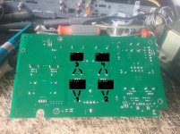
Could you please measure the voltages at the four places 1, 2, 3 and 4 on the rear side of the board? What you use as "+" and "-" is unimportant.
Attachments

Last edited:
Here is a photo of the voltage measurements as requested. I noticed tonight when I was doing the measurement of the points you have indicated as 1 and 2 (the capacitors) that there has been post production solder work done on these points. Perhaps a repair was attempted.
Attachments
Can't help but wonder. Could it be the transformer is designed for 220v and being used with 110v supply?
Here is a photo of the voltage measurements as requested. I noticed tonight when I was doing the measurement of the points you have indicated as 1 and 2 (the capacitors) that there has been post production solder work done on these points. Perhaps a repair was attempted.
Many thanks, Tony.
Now I am really confused. The points "3" and "4" are at the decoupling capacitors before the regulators. They feed the inputs of the regulators. But, they have zero voltage while at the output of the regulators there is some voltage. I have to think about what to do next 😕
Many thanks, Tony.
Now I am really confused. The points "3" and "4" are at the decoupling capacitors before the regulators. They feed the inputs of the regulators. But, they have zero voltage while at the output of the regulators there is some voltage. I have to think about what to do next 😕
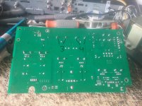
My excuses! The pins I pointed at for the measuring points "3" and "4" seem to be holding the heatsinks in place. There should evidently be no voltage difference. I will mark the correct points "3" and "4" in a following posting (I need to get my mouse to draw).
Done!
Please measure again the voltage on the two corrected measuring points "3" and "4".
Attachments
Last edited:
Can't help but wonder. Could it be the transformer is designed for 220v and being used with 110v supply?
You are exactly right. Last night I traced the serial number of the Denon DVD player and it was manufactured for the European market. I suppose I could use the power supply with a project that needs 8V or 9V so I'll put it in the closet for now.
Thanks again to everyone for all the help.
You could use it to get your required +-15v with a voltage doubler. For a headphone amplifier it would not take much in the way of reservoir caps to keep ripple in check.
- Home
- Amplifiers
- Power Supplies
- Transformer question.