Zen Mod;
Here is the Web page including the schematic for the RAKK Dac passive.
No cap.
Passive output
Here is the Web page including the schematic for the RAKK Dac passive.
No cap.
Passive output
Why avoid the drain resistors?
Distortion rises with the source impedance of whatever is driving the primary. All you have to do is look at a decent transformer datasheet, such as Jensen provides for their JT-11, which clearly documents this effect. Jensen doesn't even show figures for Rs above 600 ohms, so one can only imagine the distortion figure when driven by a very high impedance such as a JFETs drain. Lundahl even goes to such lengths as to recommend the use of current-sensing positive feedback at the driving amplifier, effectively creating a NEGATIVE driving impedance for the primary.
Yes, the reflected impedance loads the driving amplifier alright, what it doesn't do is create the effective source impedance for driving it's own primary. In addition, driving the primary from a high impedance source will form a high-pass filter in conjunction with the transformer primary inductance.
You may be driving it, but you are not driving it properly. If you feel satisfied with the resultant sound, well, okay - but the question is, why the avoidance of the drain resistors in the first place?
You can drive a transformer with a current-source if you put an appropriate load on the secondary. I've done it before. The reflected secondary loads the amplifying device. You can get flat output across the audio band as long as the secondary load is pure resistance.
Distortion rises with the source impedance of whatever is driving the primary. All you have to do is look at a decent transformer datasheet, such as Jensen provides for their JT-11, which clearly documents this effect. Jensen doesn't even show figures for Rs above 600 ohms, so one can only imagine the distortion figure when driven by a very high impedance such as a JFETs drain. Lundahl even goes to such lengths as to recommend the use of current-sensing positive feedback at the driving amplifier, effectively creating a NEGATIVE driving impedance for the primary.
Yes, the reflected impedance loads the driving amplifier alright, what it doesn't do is create the effective source impedance for driving it's own primary. In addition, driving the primary from a high impedance source will form a high-pass filter in conjunction with the transformer primary inductance.
You may be driving it, but you are not driving it properly. If you feel satisfied with the resultant sound, well, okay - but the question is, why the avoidance of the drain resistors in the first place?
Well, this was at relatively high power (2 watts) compared to this line level stuff, I guess. But at full power the second and third harmonics were more than 70db down with no feedback, so I don't think I was having any distortion problems there, and response was perfectly flat from 20-20k. Maybe it's different with line level transformers?
sorry for bringing up an old thread but how i would utilize this for balanced->single output. do i use 4 transformers after fets with 2 secondaries to ground or 2 transformers at the output of 4 zens? if the second method is correct, what about the coupling caps?
thanks😉
thanks😉
forgive me how i have drawn it...
'a' would use 1:1:1:1 as per dave's suggestion with 'g' going to output ground
'b' is a pair of 1:1 trafos for the usual bal-unbal conversion. i'd like to know if the caps can be eliminated in that case.
'a' would use 1:1:1:1 as per dave's suggestion with 'g' going to output ground
'b' is a pair of 1:1 trafos for the usual bal-unbal conversion. i'd like to know if the caps can be eliminated in that case.
An externally hosted image should be here but it was not working when we last tested it.
sorry for bringing up an old thread but how i would utilize this for balanced->single output. do i use 4 transformers after fets with 2 secondaries to ground or 2 transformers at the output of 4 zens? if the second method is correct, what about the coupling caps?
thanks😉
No.
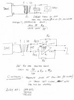
One transformer as shown in the original post. (the K1 L1 L2 L3 L4 1 command links all four inductors to a 4 winding transformer.)
For single ended simply ground one side of the secondary and for balanced you can try leaving it float and if that gives you problems youshould be able to switch the Load to a pair of 500R series resistors across the secondary (grounding the CT) and remove the two 1K resistors across the primary.
dave
B won't work because the outputs are in phase with each other.
(that is part of the neat trick of the transformer. The AC is in phase and the DC inverted so the AC sums and the DC offsets. Since it is a series circuit, the DC must remain matched and offset perfectly. No DC on the core means small transformer small gap and wide bandwidth)
dave
(that is part of the neat trick of the transformer. The AC is in phase and the DC inverted so the AC sums and the DC offsets. Since it is a series circuit, the DC must remain matched and offset perfectly. No DC on the core means small transformer small gap and wide bandwidth)
dave
sorry for being thickheaded but i'm trying to connect them to a differential output dac with r+,r-,l+,l-? wasn't your drawing only showing one channel?
wouldn't i just have to make 2 per channel, then?
i'm completely new at this. perhaps i'm missing a crucial grounding issue..
i'm completely new at this. perhaps i'm missing a crucial grounding issue..
Last edited:
it really depends what's particular DAC
generally - pos out to one end of CT primary , neg out to other end of primary
but! - where CT will be ( or not ) connected - that depends of chips used
generally - pos out to one end of CT primary , neg out to other end of primary
but! - where CT will be ( or not ) connected - that depends of chips used
i wanna try using your zen tweak on my dac, dave 😉
thanks for the reminder, zenmod. i wonder if zen is an optimal solution for 1541 since i've had negative experience with injecting current to 1543 for 0dc output. in my case, and with several iterations with different psu, it just didn't sound right.
thanks for the reminder, zenmod. i wonder if zen is an optimal solution for 1541 since i've had negative experience with injecting current to 1543 for 0dc output. in my case, and with several iterations with different psu, it just didn't sound right.
Last edited:
What does any of this have to do with the ZEN circuit at the start of the thread?
By
sorry Dave - that's usual way of thinking here in PL , where discussion is often wandering from main theme
usually fruitful praxis , while non-tech blabber is locked in Da Pub
though , I had impression that PreSapian is asking in context of having your iron ....
- Status
- Not open for further replies.
- Home
- Amplifiers
- Pass Labs
- Transformer output for zen I/V